Inst ToolsInst ToolsInst Tools
  • Courses
  • Automation
    • PLC
    • Control System
    • Safety System
    • Communication
    • Fire & Gas System
  • Instrumentation
    • Design
    • Pressure
    • Temperature
    • Flow
    • Level
    • Vibration
    • Analyzer
    • Control Valve
    • Switch
    • Calibration
    • Erection & Commissioning
  • Interview
    • Instrumentation
    • Electrical
    • Electronics
    • Practical
  • Q&A
    • Instrumentation
    • Control System
    • Electrical
    • Electronics
    • Analog Electronics
    • Digital Electronics
    • Power Electronics
    • Microprocessor
  • Request
Search
  • Books
  • Software
  • Projects
  • Process
  • Tools
  • Basics
  • Formula
  • Power Plant
  • Root Cause Analysis
  • Electrical Basics
  • Animation
  • Standards
  • 4-20 mA Course
  • Siemens PLC Course
Reading: What is Rewire Tool in Simatic Manager?
Share
Notification Show More
Font ResizerAa
Inst ToolsInst Tools
Font ResizerAa
  • Courses
  • Design
  • PLC
  • Interview
  • Control System
Search
  • Courses
  • Automation
    • PLC
    • Control System
    • Safety System
    • Communication
    • Fire & Gas System
  • Instrumentation
    • Design
    • Pressure
    • Temperature
    • Flow
    • Level
    • Vibration
    • Analyzer
    • Control Valve
    • Switch
    • Calibration
    • Erection & Commissioning
  • Interview
    • Instrumentation
    • Electrical
    • Electronics
    • Practical
  • Q&A
    • Instrumentation
    • Control System
    • Electrical
    • Electronics
    • Analog Electronics
    • Digital Electronics
    • Power Electronics
    • Microprocessor
  • Request
Follow US
All rights reserved. Reproduction in whole or in part without written permission is prohibited.
Inst Tools > Blog > PLC Tutorials > What is Rewire Tool in Simatic Manager?

What is Rewire Tool in Simatic Manager?

Last updated: March 4, 2021 12:03 pm
Editorial Staff
PLC Tutorials
No Comments
Share
2 Min Read
SHARE

This article is about to use of a rewire tool using Simatic manager.

Rewire tool is only used when you want to replace old input or output with a new one.

You can use this only in an offline window of Siemens Simatic Manager.

Rewire Tool in Simatic Manager

Do follow the below steps to know how to replace old I/Os with a new one using rewire tool.

To make changes, always remember to select the block which you want to replace with new I/Os.

If you select only a single or few blocks then changes only apply to the selected blocks and not to the whole project.

 Step 1:

Open Simatic manager. Select the “blocks”.
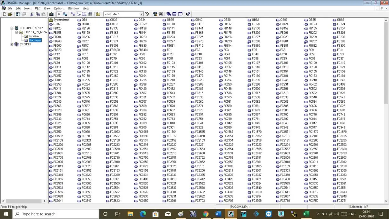
Open Simatic manager function blocks

Step 2:

To open a rewire tool, you can open it in two ways.

First, select the block and go to the option where you can find “rewire”.

Second, select block and do right click and choose “rewire”.
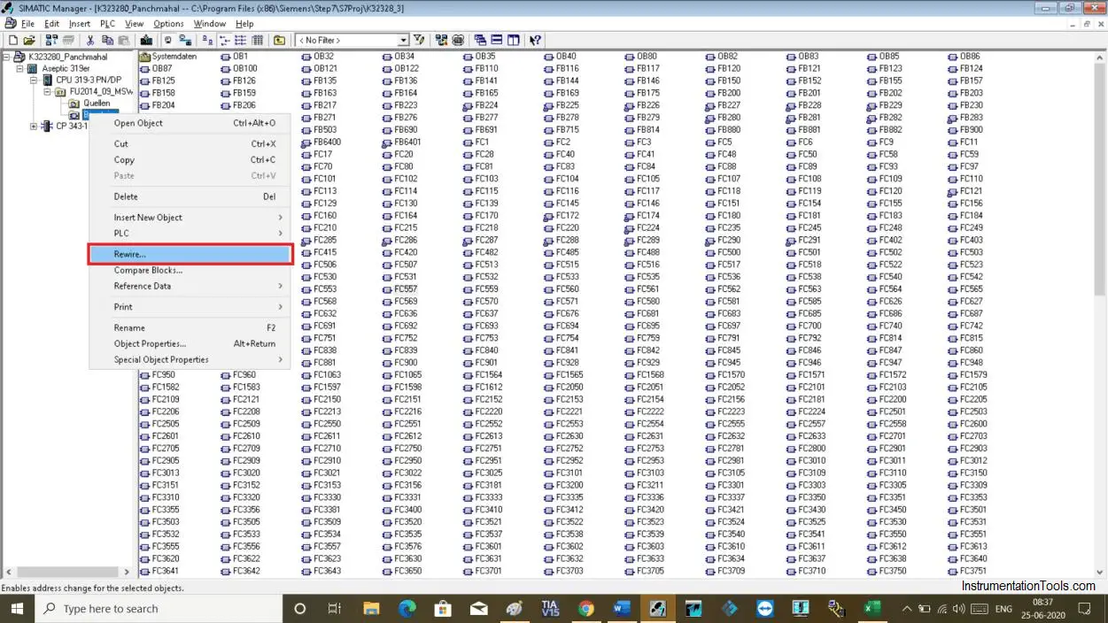
Rewire Tool

Step 3:

The following window will open up. Here, you can add old addresses and replace it with a new one.
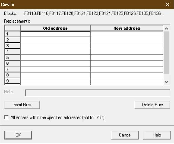
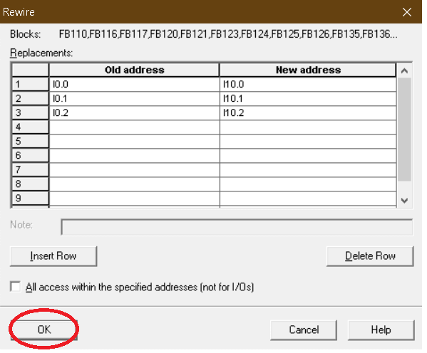
rewire tool in simatic manager

Step 4:

For example, I have changed some of the addresses as shown in the below window.

After adding addresses click “ok” to proceed.
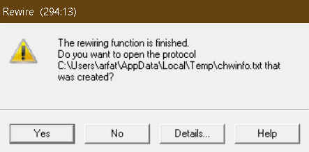
STEP7 Rewire tool

Step 5:

The following pop-up will open. Click “yes” to proceed.
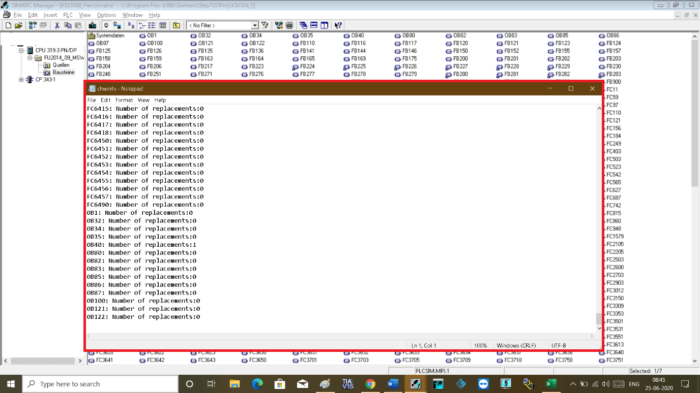
Rewiring Function

Step 6:

The following list of the changes will appear in the notepad. Where you can see the list of the block and were changes made to.

You have successfully made changes to the addresses.

Rewiring STEP 7 Simatic Manager

Author: Suhel Patel

If you liked this article, then please subscribe to our YouTube Channel for PLC and SCADA video tutorials.

You can also follow us on Facebook and Twitter to receive daily updates.

Read Next:

  • Trace Function in Tia Portal
  • Script in Intouch Scada
  • InTouch SCADA Login Security
  • Digital to Analog Conversion
  • Open Platform Communication
Don't Miss Our Updates
Be the first to get exclusive content straight to your email.
We promise not to spam you. You can unsubscribe at any time.
Invalid email address
You've successfully subscribed !

Continue Reading

How Weigh Feeder Works ?
Distributed Control System Interview Questions
PLC Timers Program
Electrical Drives – Modes, Types, Speed Control Applications
Face Mask Making Machine using PLC and HMI
PLC Timer Application in Security Camera Recording
Share This Article
Facebook Whatsapp Whatsapp LinkedIn Copy Link
Share
Leave a Comment

Leave a Reply Cancel reply

Your email address will not be published. Required fields are marked *

Stay Connected

128.3kFollowersLike
69.1kFollowersFollow
210kSubscribersSubscribe
38kFollowersFollow

Categories

Explore More

Omron PLC Online Training Course
Ladder Logic for Control of Double-acting Pneumatic Cylinder
Modbus Communication between Delta PLC with VFD
PLC Power Supply and Operating Voltages
PLC Programming Example on LED Control
While Do Statement in Structured Text PLC Program
Start Stop of one Motor from the same Push button PLC program
Inside the PLC Control Panel: How Much Do You Know?

Keep Learning

Siemens Communication between PLCs using I-Device

Tutorial: Siemens Communication between PLCs using I-Device

Configure Analog Inputs and Outputs in Delta PLC

How to Configure Analog Inputs and Outputs in Delta PLC?

What is Ladder Diagram Programming ?

PLC Controlling a Motor

PLC Motor Control Ladder Logic Programming

Difference Between Microcontroller and PLC

Difference Between Microcontroller and PLC

Ccomparator in PLC Programming

Comparator in PLC Programming

V1000 Family Programming Simulator Tool

VFD Simulator Download – Free Yaskawa V1000 Software

CRA Module in Schneider PLC

CRA Module in Schneider PLC – Remote IO Adapter Module

Learn More

Top 100 Power Electronics Questions & Answers

Top 100 Power Electronics Questions & Answers

Generator Protection Interview Questions

Generator Protection Interview Questions & Answers

Electrical Machines Questions and Answers

Reluctance Motor Quiz

Three Valve Manifold

3 Valve Manifold Operation

A typical wiring diagram from Field Transmitter to Control Room

How to Wire a Field instrument to Control Room with Example

Electromagnetic Fields Objective Questions

Electromagnetic Field MCQ

Reverse Voltage Characteristics of Photo diode

Characteristics of Photo diode

RTD installed after the Orifice Plate

Why RTD installed after the Orifice Plate ?

Menu

  • About
  • Privacy Policy
  • Copyright

Quick Links

  • Learn PLC
  • Helping Hand
  • Part Time Job

YouTube Subscribe

Follow US
All rights reserved. Reproduction in whole or in part without written permission is prohibited.
Welcome Back!

Sign in to your account

Username or Email Address
Password

Lost your password?