There are many control situations requiring actions to be initiated when a certain combination of logic functions conditions is realized in a PLC.
PLC Logic Functions
Say, for an automatic drilling machine, there might be the condition that the drill motor is to be activated when the limit switches are activated that indicate the presence of the workpiece and the drill position as being at the surface of the workpiece.
Such a situation involves the AND logic function, condition A AND condition B having both to be realized for an output to occur. This section is a consideration of such logic functions.
PLC AND LOGIC
Figure 1.7a shows a situation where an output is not energized unless two, normally open, switches are both closed. Switch A and switch B have both to be closed, which thus gives an AND logic situation.
We can think of this as representing a control system with two inputs A and B (Figure 1.7b). Only when A and B are both on is there an output. Thus if we use 1 to indicate an on signal and 0 to represent an off signal, then for there to be a 1 output we must have A and B both 1.
Such an operation is said to be controlled by a logic gate and the relationship between the inputs to a logic gate and the outputs is tabulated in a form known as a truth table. Thus for the AND gate we have:

An example of an AND gate is an interlock control system for a machine tool so that it can only be operated when the safety guard is in position and the power switched on.
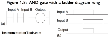
Figure 1.8a shows an AND gate system on a ladder diagram. The ladder diagram starts with j j, a normally open set of contacts labeled input A, to represent switch A and in series with it j j, another normally open set of contacts labeled input B, to represent switch B.
Also Read: Introduction to PLC Ladder Diagrams
The line then terminates with O to represent the output. For there to be an output, both input A and input B have to occur, i.e., input A and input B contacts have to be closed (Figure 1.8b). In general:
On a ladder diagram contacts in a horizontal rung, i.e., contacts in series, represent the logical AND operations.
PLC OR LOGIC
Figure 1.9a shows an electrical circuit where an output is energized when switch A or B, both normally open, are closed.
This describes an OR logic gate (Figure 1.9b) in that input A or input B must be on for there to be an output.
The truth table is:

Figure 1.10a shows an OR logic gate system on a ladder diagram, Figure 1.10b showing an equivalent alternative way of drawing the same diagram.
The ladder diagram starts with j j, normally open contacts labeled input A, to represent switch A and in parallel with it j j, normally open contacts labeled input B, to represent switch B.
Either input A or input B have to be closed for the output to be energized
(Figure 1.10c). The line then terminates with O to represent the output. In general:
Alternative paths provided by vertical paths from the main rung of a ladder diagram, i.e., paths in parallel represent logical OR operations.
An example of an OR gate control system is a conveyor belt transporting bottled products to packaging where a deflector plate is activated to deflect bottles into a reject bin if either the weight is not within certain tolerances or there is no cap on the bottle.

PLC NOT LOGIC
Figure 1.11a shows an electrical circuit controlled by a switch that is normally closed. When there is an input to the switch, it opens and there is then no current in the circuit.
This illustrates a NOT gate in that there is an output when there is no input and no output when there is an input (Figure 1.11c). The gate is sometimes referred to as an inverter.
The truth table is:
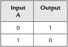
Figure 11.11b shows a NOT gate system on a ladder diagram. The input A contacts are shown as being normally closed.
This is in series with the output ( ). With no input to input A, the contacts are closed and so there is an output. When there is an input to input A, it opens and there is then no output.
An example of a NOT gate control system is a light that comes on when it becomes dark, i.e., when there is no light input to the light sensor there is an output.

PLC NAND LOGIC
Suppose we follow an AND gate with a NOT gate (Figure 1.12a). The consequence of having the NOT gate is to invert all the outputs from the AND gate.
An alternative, which gives exactly the same results, is to put a NOT gate on each input and then follow that with OR (Figure 1.12b).
The same truth table occurs, namely:

Both the inputs A and B have to be 0 for there to be a 1 output.
There is an output when input A and input B are not 1.
The combination of these gates is termed a NAND gate (Figure 1.13).

An example of a NAND gate control system is a warning light that comes on if, with a machine tool, the safety guard switch has not been activated and the limit switch signaling the presence of the workpiece has not been activated.
PLC NOR LOGIC
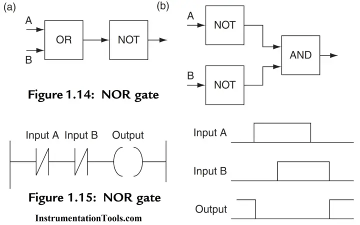
Suppose we follow an OR gate by a NOT gate (Figure 1.14a).
The consequence of having the NOT gate is to invert the outputs of the OR gate.
An alternative, which gives exactly the same results, is to put a NOT gate on each input and then an AND gate for the resulting inverted inputs (Figure 1.14b).
The following is the resulting truth table:
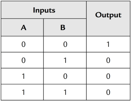
The combination of OR and NOT gates is termed a NOR gate. There is an output when neither input A or input B is 1.
Figure 1.15 shows a ladder diagram of a NOR system.
When input A and input B are both not activated, there is a 1 output. When either X400 or X401 are 1 there is a 0 output.
PLC Exclusive OR (XOR) LOGIC
The OR gate gives an output when either or both of the inputs are 1.
Sometimes there is, however, a need for a gate that gives an output when either of the inputs is 1 but not when both are 1, i.e., has the truth table:
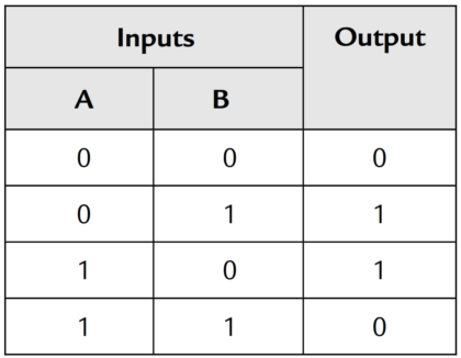
Such a gate is called an Exclusive OR or XOR gate.
One way of obtaining such a gate is by using NOT, AND and OR gates as shown in Figure 1.16.
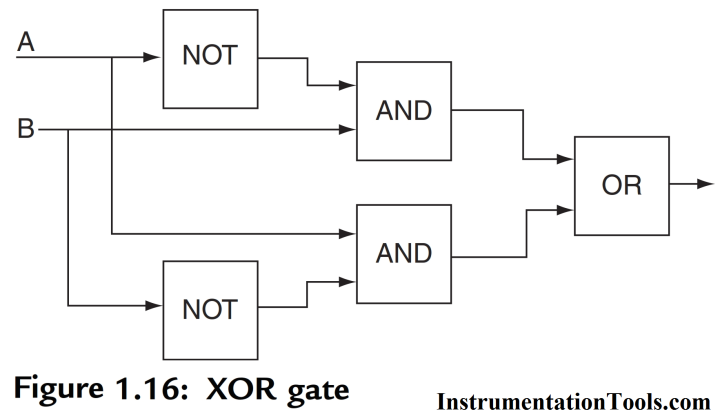
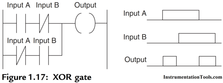
Figure 1.17 shows a ladder diagram for an XOR gate system. When input A and input B are not activated then there is 0 output.
When just input A is activated, then the upper branch results in the output being 1. When just input B is activated, then the lower branch results in the output being 1.
When both input A and input B are activated, there is no output.
In this example of a logic gate, input A and input B have two sets of contacts in the circuits, one set being normally open and the other normally closed.
With PLC programming, each input may have as many sets of contacts as necessary.
PLC Exclusive NOR (XNOR) LOGIC
Also Read: Normally Closed Contact for Stop Button
If you liked this article, then please subscribe to our YouTube Channel for PLC and SCADA video tutorials.
You can also follow us on Facebook and Twitter to receive daily updates.
Read Next:






Send me plz all PLC programming from basic
Send me please all PLC programming
If you want all the ladder logic programs, search about the gates in plc you will get the whole programming and implementation of all gates.
Send all plc programs
What is LOA in PLC system
i think there is a mistake in Nand and Nor ladder logic..pls check it..