Inst ToolsInst ToolsInst Tools
  • Courses
  • Automation
    • PLC
    • Control System
    • Safety System
    • Communication
    • Fire & Gas System
  • Instrumentation
    • Design
    • Pressure
    • Temperature
    • Flow
    • Level
    • Vibration
    • Analyzer
    • Control Valve
    • Switch
    • Calibration
    • Erection & Commissioning
  • Interview
    • Instrumentation
    • Electrical
    • Electronics
    • Practical
  • Q&A
    • Instrumentation
    • Control System
    • Electrical
    • Electronics
    • Analog Electronics
    • Digital Electronics
    • Power Electronics
    • Microprocessor
  • Request
Search
  • Books
  • Software
  • Projects
  • Process
  • Tools
  • Basics
  • Formula
  • Power Plant
  • Root Cause Analysis
  • Electrical Basics
  • Animation
  • Standards
  • 4-20 mA Course
  • Siemens PLC Course
Reading: ISA Codes & Symbols for Process Instrumentation
Share
Font ResizerAa
Inst ToolsInst Tools
Font ResizerAa
  • Courses
  • Design
  • PLC
  • Interview
  • Control System
Search
  • Courses
  • Automation
    • PLC
    • Control System
    • Safety System
    • Communication
    • Fire & Gas System
  • Instrumentation
    • Design
    • Pressure
    • Temperature
    • Flow
    • Level
    • Vibration
    • Analyzer
    • Control Valve
    • Switch
    • Calibration
    • Erection & Commissioning
  • Interview
    • Instrumentation
    • Electrical
    • Electronics
    • Practical
  • Q&A
    • Instrumentation
    • Control System
    • Electrical
    • Electronics
    • Analog Electronics
    • Digital Electronics
    • Power Electronics
    • Microprocessor
  • Request
Follow US
All rights reserved. Reproduction in whole or in part without written permission is prohibited.
Inst Tools > Blog > Common > ISA Codes & Symbols for Process Instrumentation

ISA Codes & Symbols for Process Instrumentation

Last updated: August 21, 2016 7:01 am
Editorial Staff
Common
1 Comment
Share
5 Min Read
SHARE

The primary purpose of using codes and symbols is to enable the various instrument functions required in a process to be clearly and concisely represented on Process Flow Diagrams (PFD) and on Pipeline and Instrumentation Drawings (P&ID).

The measuring instrument and control device function codes and symbols indicate which process parameter is being measured, the relative locations of the measurement and control devices and the permissible limits applicable to certain variable process conditions.

In cases where supervisory computer systems are installed in a system, special symbols are used to indicate the computer and the instruments, which are connected to it.

For instance, letter codes and symbols permit the following instrument; functions to be graphically represented.

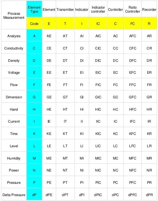
Process Monitoring Instrument Codes

– Flow rate (F)

– Level (L)

– Pressure (P)

– Quality (Q)

– Speed (S)

– Temperature (T)

These codes are integrated with various symbols to distinguish between indicators, recorders and in certain cases, their geographical locations.

At the end of this section, there are several sheets contain wide range of the applicable instrument symbols and abbreviations.

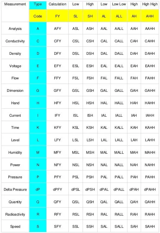
Emergency or Safety Instrument Codes

A list is given below, for the abnormal conditions, which must be measured by function qualification instruments. State display or alarm signals from such instruments are for the purpose of alerting the process operator, thus enabling corrective action to be taken. In cases of emergency or to safeguard vital equipment, the instruments automatically initiate trip or shutdown actions.

– High level (H) initiates an alarm.

– Extreme high level (HH) trips the inlet valve shut.

– Low level (L) initiates an alarm.

– Extreme low level (LL) trips the outlet valve shut.

Low flow (L) initiates an alarm and may also open a minimum flow spill-back or recycle valve to prevent the pump from overheating. Extreme low flow (LL) trips the pump motor to prevent damage.

High-pressure (H) increases the overhead condenser coolant flow. Extreme high pressure (HH) initiates an alarm and opens a vent valve to flare.

High temperature (H) initiates an alarm. Extreme high temperature (HH) trips the fuel inlet valves to protect the furnace coil from overheating.

Structure of the Instrument Codes

In general, every conventional measuring or controlling instrument Installed in a process unit is identified by three separate codes as follows.

A location number code indicates the specific process unit in which the instrument is installed.

A function letter code indicates the property or process variable being measured or controlled.

A serial number code identifies the specific instrument and therefore prevents confusion when there are several Instruments In a single process unit, each having the same function letter code.

The combination of the three codes is known as the Instrument tag number, which has the basic format

xx a – yyy

TAG NUMBERS

“xx” is a two-digit number used to identify the process unit.

‘a’ is a letter code containing two or more capital letters and is used to identify the instrument function.

‘yyy’ is a three-digit number used to identify the particular instrument.

When the instrument code or tag number is written on a drawing or document, a dash is inserted between the ‘a’ and the ‘yyy’ sections of the format. For example, a pressure indicating controller installed in a process unit coded 11 and identified by serial number 1101, is described in written form as 11 – PIC – 1101.

In the case of the same tag numbers, the process pressure correcting element, usually a control valve, often has the same tag number as the controller.

However, when the controller operates two valves in a split range mode, the valves are tagged and numbered consecutively,

ISA Codes for Process Instrumentation

ISA Codes for Process Instrumentation
ISA Codes for Process Instrumentation -1
ISA Codes for Process Instrumentation
Don't Miss Our Updates
Be the first to get exclusive content straight to your email.
We promise not to spam you. You can unsubscribe at any time.
Invalid email address
You've successfully subscribed !

Continue Reading

Field Instrumentation Tips
Benefits of IoT in the Manufacturing Industry
Types of Angular Velocity Measurement
How to Test a Battery using a Multimeter?
What is a Flange Gasket ?
Types of Sensors Used in Automobiles
Share This Article
Facebook Whatsapp Whatsapp LinkedIn Copy Link
Share
1 Comment
  • Vasily says:
    August 25, 2022 at 10:08 am

    Hi There, I have not found the reference to the information provided

    Reply

Leave a Reply Cancel reply

Your email address will not be published. Required fields are marked *

Stay Connected

128.3kFollowersLike
69.1kFollowersFollow
210kSubscribersSubscribe
38kFollowersFollow

Categories

Explore More

Hydraulic and Pneumatic P&ID Diagrams and Schematics
Introduction to Urea Bagging Machine
What is PDCA? – Industrial Maintenance
Single Block and Bleed Valve Manifold Operation
Automotive Rail Rapid Transit
9 Life-Saving Rules for Oil and Gas Industry
7 Investments for Single Mothers
Difference Between HDD and SSD

Keep Learning

Ultrapure Water in the Semiconductor Industry

Ultrapure Water in the Semiconductor Industry

Laser Doppler anemometer

Laser Doppler Anemometer

CNC Machine Tools Problems and Solutions

Common Problems With CNC Machine Tools & Their Solutions

Moving Coil Type Velocity Transducer

Moving Coil Type Velocity Transducer

Working of Air Compressor

Working of Air Compressor – Types – Control Techniques

smart-transmitters-advanced-diagnostics

Smart Transmitters Advanced Diagnostics

Electronic Symbols

Electronic Diagrams, Prints and Schematics

Career Scope in Electronics Engineering

Career Scope in Electronics Engineering

Learn More

PROFIBUS is also a Master Slave protocol

Compare Modbus, Fieldbus, and Profibus

Basic Transistor Amplifier Circuit Principle

Basic Transistor Amplifier Circuit Principle

Orifice Plate Flow Requirements

What are the Orifice Plate Flow Requirements?

phototransistor symbols

Phototransistor Working Principle

Construction of Megger

What is a Megger? Principle, Advantages, Disadvantages, Applications

Off load Tap Changer Principle

Transformer Tap Changing Working Principle

How Engineers Effectively do Problem-solve and Troubleshoot

How Engineers Effectively do Problem-solve and Troubleshoot?

pH Analyzer Calibration and Troubleshooting

pH Analyzer Calibration and Troubleshooting

Menu

  • About
  • Privacy Policy
  • Copyright

Quick Links

  • Learn PLC
  • Helping Hand
  • Part Time Job

YouTube Subscribe

Follow US
All rights reserved. Reproduction in whole or in part without written permission is prohibited.
Welcome Back!

Sign in to your account

Username or Email Address
Password

Lost your password?