Inst ToolsInst ToolsInst Tools
  • Courses
  • Automation
    • PLC
    • Control System
    • Safety System
    • Communication
    • Fire & Gas System
  • Instrumentation
    • Design
    • Pressure
    • Temperature
    • Flow
    • Level
    • Vibration
    • Analyzer
    • Control Valve
    • Switch
    • Calibration
    • Erection & Commissioning
  • Interview
    • Instrumentation
    • Electrical
    • Electronics
    • Practical
  • Q&A
    • Instrumentation
    • Control System
    • Electrical
    • Electronics
    • Analog Electronics
    • Digital Electronics
    • Power Electronics
    • Microprocessor
  • Request
Search
  • Books
  • Software
  • Projects
  • Process
  • Tools
  • Basics
  • Formula
  • Power Plant
  • Root Cause Analysis
  • Electrical Basics
  • Animation
  • Standards
  • 4-20 mA Course
  • Siemens PLC Course
Reading: Multiphase Flow Meter Calibration Procedure
Share
Font ResizerAa
Inst ToolsInst Tools
Font ResizerAa
  • Courses
  • Design
  • PLC
  • Interview
  • Control System
Search
  • Courses
  • Automation
    • PLC
    • Control System
    • Safety System
    • Communication
    • Fire & Gas System
  • Instrumentation
    • Design
    • Pressure
    • Temperature
    • Flow
    • Level
    • Vibration
    • Analyzer
    • Control Valve
    • Switch
    • Calibration
    • Erection & Commissioning
  • Interview
    • Instrumentation
    • Electrical
    • Electronics
    • Practical
  • Q&A
    • Instrumentation
    • Control System
    • Electrical
    • Electronics
    • Analog Electronics
    • Digital Electronics
    • Power Electronics
    • Microprocessor
  • Request
Follow US
All rights reserved. Reproduction in whole or in part without written permission is prohibited.
Inst Tools > Blog > Calibration > Multiphase Flow Meter Calibration Procedure

Multiphase Flow Meter Calibration Procedure

Multiphase Flow Meter calibration using gamma densitometer, capacitive, and inductance sensor to determine the fluid composition and speed of flow.

Last updated: November 2, 2023 12:00 pm
Editorial Staff
Calibration Flow Measurement
No Comments
Share
6 Min Read
SHARE

PhaseWatcher fixed multiphase well production monitoring equipment uses Vx technology to continuously measure flow rates in wells exhibiting up to three-phase flow for production monitoring.

Contents
Multiphase Flow MeterPrincipleCalibration of MPFMCalibration of Gamma DetectorCalibration of Differential Pressure TransmitterCalibration of Pressure and Temperature Transmitters

Vx multiphase well testing technology combines an instrumented venture with a dual-energy fraction meter which measures the total mass flow rate and the fractions of gas, oil, and water which in turn determines individual flow rates.

Vx technology functions without the need for separation or an upstream mixing device.

Multiphase Flow Meter

Multiphase Flow Meter Calibration Procedure

The PhaseWatcher meter consists of two main sections:

  • The Measuring Section
  • The Data Acquisition Flow Computer

Make: Schlumberger

Model No: Phase Watcher Vx (VXPW N1-65HT)

Flow Measurement System (Specific Type): Venturi & Dual Energy Gamma Ray 

Flow meters using Vx technology require no process control because they are insensitive to changes in flow rate, phase holdup, and pressure regime. The heart of these measurement systems is fast data acquisition at the venture section of a multi-energy gamma ray holdup meter with no moving parts.

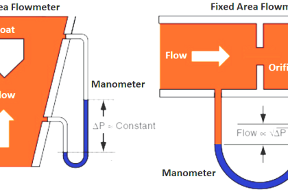
The venturi section can be mounted on a portable skid for temporary installations or installed as a permanent monitoring device. The mass flow rate is measured conventionally using absolute and differential pressure sensors.

Principle

The measuring principle is based on a total mass flow rate measured by a venturi meter and the individual phase fractions measured by a dual-energy gamma fraction meter. The Measuring Section contains the venturi meter and the dual energy gamma fraction meter.

The data acquired in the Measuring Section are processed in the Data Acquisition Flow Computer, which computes the line pressure and temperature and the individual phase flow rates. The data can be transmitted to a service computer or to a supervisory system via a digital serial link (RS 422 or RS 232) and Modbus Protocol.

Calibration of MPFM flow meter

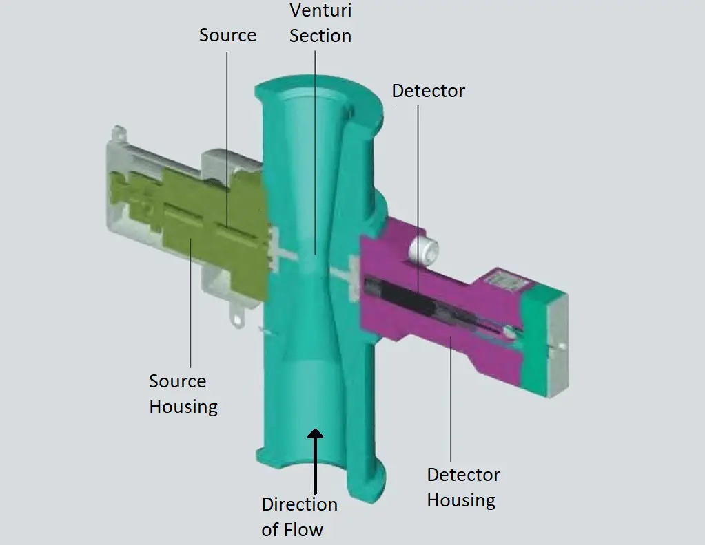
Image Courtesy: Schlumberger

PhaseWatcher breaks up the flow regime into a turbulent mixture and uses high-frequency measurements to precisely measure the individual phase fractions. In this manner, the PhaseWatcher measurements are unaffected by any flow pattern that appears in multiphase flow lines.

The PhaseWatcher MPFM utilizes two energy levels from a Barium133 source for the fraction measurements in multiphase flow.

Calibration of MPFM

PhaseWatcher was developed around physical measurements, rather than flow modeling. Hence it does not require any flowing calibration.

Calibration of Gamma Detector

Calibration of the gamma detector is normally performed on air at atmospheric conditions prior to installation; however, it can also be performed on any other fluid as long as its properties are known. This way a remotely operated multiphase flow meter can be calibrated simply on the fluid which may settle out inside the multiphase flow meter after closing an upstream or downstream valve.

Even without being properly calibrated, the gamma meter will identify whether the fluid is oil, water or gas, and the appropriate static single-point calibration can be performed.

Calibration of Differential Pressure Transmitter

The differential pressure transmitter is calibrated by performing a single-point static measurement following the same procedure as for the gamma detector. The differential pressure at static conditions equals the hydrostatic height between the two sensor elements.

The pressure ports in the venturi section are arranged with a facility that allows flushing. This feature can reduce the risk of pressure port blockages. Flushing procedures are part of normal operational routines.

Flushing media will be high-pressure fluid supplied through a dedicated hydraulic line which can also be used to fill the measuring section with the same fluid for calibration purposes. The high-pressure flushing media can be either hydraulic control fluid, chemical injection fluid, methanol, or similar.

The pressure ports can also be fitted with remote seals, which prevent the mixing of process fluids and the hydraulic control fluid. Fitting remote seals eliminates the requirement for flushing.

Calibration of Pressure and Temperature Transmitters

For many applications, small deviations in temperature and pressure readings have little impact on the flow rate computations. A simple comparison with the pressure and temperature readings taken at an X-mas tree or nearby manifold will be accurate enough.

Alternatively, when the meter is isolated and pressurized through the flushing line, the pressure transmitter can be calibrated using a deadweight tester connected to the flushing line.

If you liked this article, then please subscribe to our YouTube Channel for Instrumentation, Electrical, PLC, and SCADA video tutorials.

You can also follow us on Facebook and Twitter to receive daily updates.

Read Next:

  • Turndown Ratio for Flow Meter 
  • Flow Meter K-factor Calculations
  • Turbine Flow Meter Verification
  • Coriolis Flow Meter Uncertainty
  • Types of Vortex Flow Sensors
Don't Miss Our Updates
Be the first to get exclusive content straight to your email.
We promise not to spam you. You can unsubscribe at any time.
Invalid email address
You've successfully subscribed !

Continue Reading

Difference between Calibration and Ranging
Instrumentation Engineer’s Calibration Mistakes
Paddle Wheel Flow Meters – Principle, Advantages, Limitations
Top Questions on Bernoulli’s Principle in Flow Meters
Temperature Sensor calibration procedure
Factors Affecting the Performance of Ultrasonic Flow Meters
Share This Article
Facebook Whatsapp Whatsapp LinkedIn Copy Link
Share
Leave a Comment

Leave a Reply Cancel reply

Your email address will not be published. Required fields are marked *

Stay Connected

128.3kFollowersLike
69.1kFollowersFollow
210kSubscribersSubscribe
38kFollowersFollow

Categories

Explore More

Calibration MCQ – Terminology and Glossary Questions
Pressure Transmitter Calibration at the bench
Level Transmitter Calibration Procedure
V Cone Flow Meter – Principle, Advantages, Disadvantages
Orifice Plate Questions and Answers
Calibration of Displacer Level Transmitter
How to Create Calibration Records?
Instrument Calibration Lab Exercise

Keep Learning

Impulse line - Purpose & Tapping Point Location

Impulse Line – Purpose & Tapping Point Location

vortex flow transmitter

What is a Vortex Flow Meter?

Hot wire Anemometer Principle

Hot Wire Anemometer Principle and Types

Transit Time flow meter Theory

Transit Time Flow Meter Principle

Instrument Linearity Error

Instrument Errors – Zero, Span, Linearity

Magnetostrictive Level Transmitter Calibration

Magnetostrictive Level Transmitter Calibration Procedure

Impeller Flow Sensor

Impeller Flow Sensor Working Principle and Animation

As-Found and As-Left data during Calibration

Why it is important to note As-Found and As-Left data during Calibration?

Learn More

What is Gas Chromatography

What is Gas Chromatography?

Digital Electronics Multiple Choice Questions

Flip Flops Objective Questions – Part 2

What is an HRC Fuse

What is an HRC Fuse? – Material, Types, Advantages

SIS Verification & Validation - Safety Instrumented System

SIS Verification & Validation – Safety Instrumented System

Purpose of Isolation valve

What are Isolation valves? – Purpose, Types, Configurations

Schematic Diagram

Schematic Diagram

RSLogix5000 PLC Program Backup procedure

How to Design a Motor Faceplate in Graphics - SCADA Tutorials

How to Design a Motor Faceplate in Graphics? – SCADA Tutorials

Menu

  • About
  • Privacy Policy
  • Copyright

Quick Links

  • Learn PLC
  • Helping Hand
  • Part Time Job

YouTube Subscribe

Follow US
All rights reserved. Reproduction in whole or in part without written permission is prohibited.
Welcome Back!

Sign in to your account

Username or Email Address
Password

Lost your password?