Inst ToolsInst ToolsInst Tools
  • Courses
  • Automation
    • PLC
    • Control System
    • Safety System
    • Communication
    • Fire & Gas System
  • Instrumentation
    • Design
    • Pressure
    • Temperature
    • Flow
    • Level
    • Vibration
    • Analyzer
    • Control Valve
    • Switch
    • Calibration
    • Erection & Commissioning
  • Interview
    • Instrumentation
    • Electrical
    • Electronics
    • Practical
  • Q&A
    • Instrumentation
    • Control System
    • Electrical
    • Electronics
    • Analog Electronics
    • Digital Electronics
    • Power Electronics
    • Microprocessor
  • Request
Search
  • Books
  • Software
  • Projects
  • Process
  • Tools
  • Basics
  • Formula
  • Power Plant
  • Root Cause Analysis
  • Electrical Basics
  • Animation
  • Standards
  • 4-20 mA Course
  • Siemens PLC Course
Reading: Classification of Bridge Circuits
Share
Font ResizerAa
Inst ToolsInst Tools
Font ResizerAa
  • Courses
  • Design
  • PLC
  • Interview
  • Control System
Search
  • Courses
  • Automation
    • PLC
    • Control System
    • Safety System
    • Communication
    • Fire & Gas System
  • Instrumentation
    • Design
    • Pressure
    • Temperature
    • Flow
    • Level
    • Vibration
    • Analyzer
    • Control Valve
    • Switch
    • Calibration
    • Erection & Commissioning
  • Interview
    • Instrumentation
    • Electrical
    • Electronics
    • Practical
  • Q&A
    • Instrumentation
    • Control System
    • Electrical
    • Electronics
    • Analog Electronics
    • Digital Electronics
    • Power Electronics
    • Microprocessor
  • Request
Follow US
All rights reserved. Reproduction in whole or in part without written permission is prohibited.
Inst Tools > Blog > Electronic Devices & Circuits > Classification of Bridge Circuits

Classification of Bridge Circuits

Last updated: April 1, 2018 9:51 am
Editorial Staff
Electronic Devices & Circuits
No Comments
Share
1 Min Read
SHARE

The two Types of bridges are,

  1. D.C Bridges
  2. A.C Bridges

The D.C bridges are used to measure the resistance while the A.C bridges are used to measure the impedances consisting capacitance and inductances. The D.C bridges use the D.C voltages as the excitation voltage while the A.C bridges use the alternating voltage as the excitation voltage.

Classification of Bridge Circuits

The two types of D.C bridges
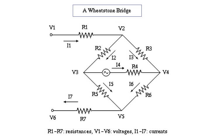
  1. Wheatstone Bridge
  2. Kelvin Bridge

The various types of A.C Bridges are,

  1. Capacitance Comparison Bridge
  2. Inductance Comparison Bridge
  3. Maxwell’s Bridge
  4. Hay’s Bridge
  5. Anderson Bridge
  6. Schering Bridge
  7. Wien Bridge
Don't Miss Our Updates
Be the first to get exclusive content straight to your email.
We promise not to spam you. You can unsubscribe at any time.
Invalid email address
You've successfully subscribed !

Continue Reading

Transistor Emitter Feedback Bias
What is a Filter Circuit ?
Applications of Photo diodes
Comparison of Half wave Rectifiers and Full wave Rectifiers
Comparison of Transistor Configurations
Working of NPN Transistor
Share This Article
Facebook Whatsapp Whatsapp LinkedIn Copy Link
Share
Leave a Comment

Leave a Reply Cancel reply

Your email address will not be published. Required fields are marked *

Stay Connected

128.3kFollowersLike
69.1kFollowersFollow
210kSubscribersSubscribe
38kFollowersFollow

Categories

Explore More

Transistor Biasing
pi filter Operation
Operation of Zener Diode Voltage Regulator
Tunnel Diode Working Principle
Difference between ideal diode & conventional diode
What is Kirchhoff’s Current Law
Capacitor Filter Working Principle
Laser Diode Working Principle

Keep Learning

Transistors Questions & Answers

Transistors Questions & Answers

Peak Inverse Voltage of Center Tap Rectifier

Peak Inverse Voltage of Center Tap Rectifier

Short Circuit and Open Circuit

Short Circuit and Open Circuit

Transistor as Switch in Cut off region

Transistor as a Switch Working Principle

Transistor Stabilisation

Transistor Stabilisation

Capacitor Filter Operation

Capacitor Filter Operation

transistor-biasing-circuits

Summary Of Transistor Bias Circuits

diode-clamper-circuit

Full Wave Voltage Doubler using Diodes

Learn More

Pressure Gauge Selection

Pressure Gauge Selection

Series-Wound DC Generator Principle

Series-Wound DC Generators

State Variable Analysis and Design

Pole Placement by State Feedback

How to Test a Battery using Multimeter

How to Test a Battery using a Multimeter?

Control of Double-acting Pneumatic Cylinder

Ladder Logic for Control of Double-acting Pneumatic Cylinder

Power Electronics Objective Questions

3 Phase Bridge Inverters Quiz

Example of PID Control Instruction

How to Configure PID in Siemens PLC?

Commissioning Checklist for Industrial Automation System

Commissioning Checklists for Industrial Automation Systems

Menu

  • About
  • Privacy Policy
  • Copyright

Quick Links

  • Learn PLC
  • Helping Hand
  • Part Time Job

YouTube Subscribe

Follow US
All rights reserved. Reproduction in whole or in part without written permission is prohibited.
Welcome Back!

Sign in to your account

Username or Email Address
Password

Lost your password?