Inst ToolsInst ToolsInst Tools
  • Courses
  • Automation
    • PLC
    • Control System
    • Safety System
    • Communication
    • Fire & Gas System
  • Instrumentation
    • Design
    • Pressure
    • Temperature
    • Flow
    • Level
    • Vibration
    • Analyzer
    • Control Valve
    • Switch
    • Calibration
    • Erection & Commissioning
  • Interview
    • Instrumentation
    • Electrical
    • Electronics
    • Practical
  • Q&A
    • Instrumentation
    • Control System
    • Electrical
    • Electronics
    • Analog Electronics
    • Digital Electronics
    • Power Electronics
    • Microprocessor
  • Request
Search
  • Books
  • Software
  • Projects
  • Process
  • Tools
  • Basics
  • Formula
  • Power Plant
  • Root Cause Analysis
  • Electrical Basics
  • Animation
  • Standards
  • 4-20 mA Course
  • Siemens PLC Course
Reading: Resistivity
Share
Font ResizerAa
Inst ToolsInst Tools
Font ResizerAa
  • Courses
  • Design
  • PLC
  • Interview
  • Control System
Search
  • Courses
  • Automation
    • PLC
    • Control System
    • Safety System
    • Communication
    • Fire & Gas System
  • Instrumentation
    • Design
    • Pressure
    • Temperature
    • Flow
    • Level
    • Vibration
    • Analyzer
    • Control Valve
    • Switch
    • Calibration
    • Erection & Commissioning
  • Interview
    • Instrumentation
    • Electrical
    • Electronics
    • Practical
  • Q&A
    • Instrumentation
    • Control System
    • Electrical
    • Electronics
    • Analog Electronics
    • Digital Electronics
    • Power Electronics
    • Microprocessor
  • Request
Follow US
All rights reserved. Reproduction in whole or in part without written permission is prohibited.
Inst Tools > Blog > Electrical Theory > Resistivity

Resistivity

Last updated: July 23, 2018 10:31 am
Editorial Staff
Electrical Theory
No Comments
Share
2 Min Read
SHARE

Resistivity is defined as the measure of the resistance a material imposes on current flow. The resistance of a given length of conductor depends upon the resistivity of that material, the length of the conductor, and the cross-sectional area of the conductor, according to Equation.

Resistivity

where

R = resistance of conductor, Ω
ρ = specific resistance or resistivity cm-Ω/ft
L = length of conductor, ft
A = cross-sectional area of conductor, cm

The resistivity ρ (rho) allows different materials to be compared for resistance, according to their nature, without regard to length or area. The higher the value of ρ, the higher the resistance.

Table 1 gives resistivity values for metals having the standard wire size of one foot in length and a cross-sectional area of 1 cm.

Properties of Conducting Materials

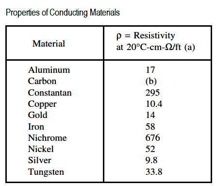
(a) Precise values depend on exact composition of material.

(b) Carbon has 2500-7500 times the resistance of copper.

Temperature Coefficient of Resistance

Temperature coefficient of resistance, α (alpha), is defined as the amount of change of the resistance of a material for a given change in temperature. A positive value of α indicates that R increases with temperature; a negative value of α indicates R decreases; and zero α indicates that R is constant. Typical values are listed in Table 2.

Temperature Coefficients for Various Materials

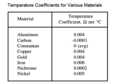
For a given material, α may vary with temperature; therefore, charts are often used to describe how resistance of a material varies with temperature.

An increase in resistance can be approximated from equation.

Temperature Coefficient of Resistance

where

Rt = higher resistance at higher temperatures
R0 = resistance at 0 degc temperature
α = temperature coefficient
∆T = change in temperature

Don't Miss Our Updates
Be the first to get exclusive content straight to your email.
We promise not to spam you. You can unsubscribe at any time.
Invalid email address
You've successfully subscribed !

Continue Reading

Applying Kirchhoff’s Voltage Law
Rectifiers, Forward Bias and Reverse Bias
Transformer Losses and Efficiency
Reading Electrical Schematics
Motor Controllers
Series Resistance
Share This Article
Facebook Whatsapp Whatsapp LinkedIn Copy Link
Share
Leave a Comment

Leave a Reply Cancel reply

Your email address will not be published. Required fields are marked *

Stay Connected

128.3kFollowersLike
69.1kFollowersFollow
210kSubscribersSubscribe
38kFollowersFollow

Categories

Explore More

Shunt-Wound DC Generators
Types of Batteries
Calculate Power in Series RL Circuit
Battery Operation : Series and Parallel
AC Motor Theory
Series Short Circuit Faults
Transformer Efficiency
Low Voltage Protection (LVP) and Low Voltage Release (LVR)

Keep Learning

Inductive Time Constant

Inductive Time Constant

Auto Transformer Schematic

Classification of Transformers

Types of Fuses

Electrical System Components and Protection Devices

Left-Hand Rule for Current-Carrying Conductors

DC Motor Theory

Carbon Atom

What is Electricity ?

Induction Motor Torque

AC Induction Motor Slip

Electrical Wiring Terminology

Electrical Wiring Terminology

AC Generator Nameplate Ratings

AC Generator Nameplate Ratings

Learn More

Industrial Automation Protocols

Industrial Automation Protocols

Control System Vendor Internal Test Procedures

Vendor View of Supplying Industrial Process Control & Safety Systems

field-mounted thermocouple

Thermocouple Extension Wires

Difference Between AIS and GIS Panels

Difference Between AIS and GIS Panels

PLC Boxes Sorting Based on Height

PLC Programming: Sorting and Distribution of Boxes by Height

Instrumentation Engineering Root Cause Analysis

Instrumentation Engineering Problems Solved – Root Cause Analysis

Interview Questions on Battery Testing

Interview Questions on Battery Testing

failure rate of a component - 1

Failure rate and MTBF of Safety Instrumented Systems

Menu

  • About
  • Privacy Policy
  • Copyright

Quick Links

  • Learn PLC
  • Helping Hand
  • Part Time Job

YouTube Subscribe

Follow US
All rights reserved. Reproduction in whole or in part without written permission is prohibited.
Welcome Back!

Sign in to your account

Username or Email Address
Password

Lost your password?