Inst ToolsInst ToolsInst Tools
  • Courses
  • Automation
    • PLC
    • Control System
    • Safety System
    • Communication
    • Fire & Gas System
  • Instrumentation
    • Design
    • Pressure
    • Temperature
    • Flow
    • Level
    • Vibration
    • Analyzer
    • Control Valve
    • Switch
    • Calibration
    • Erection & Commissioning
  • Interview
    • Instrumentation
    • Electrical
    • Electronics
    • Practical
  • Q&A
    • Instrumentation
    • Control System
    • Electrical
    • Electronics
    • Analog Electronics
    • Digital Electronics
    • Power Electronics
    • Microprocessor
  • Request
Search
  • Books
  • Software
  • Projects
  • Process
  • Tools
  • Basics
  • Formula
  • Power Plant
  • Root Cause Analysis
  • Electrical Basics
  • Animation
  • Standards
  • 4-20 mA Course
  • Siemens PLC Course
Reading: Calculate Power in Series RL Circuit
Share
Notification Show More
Font ResizerAa
Inst ToolsInst Tools
Font ResizerAa
  • Courses
  • Design
  • PLC
  • Interview
  • Control System
Search
  • Courses
  • Automation
    • PLC
    • Control System
    • Safety System
    • Communication
    • Fire & Gas System
  • Instrumentation
    • Design
    • Pressure
    • Temperature
    • Flow
    • Level
    • Vibration
    • Analyzer
    • Control Valve
    • Switch
    • Calibration
    • Erection & Commissioning
  • Interview
    • Instrumentation
    • Electrical
    • Electronics
    • Practical
  • Q&A
    • Instrumentation
    • Control System
    • Electrical
    • Electronics
    • Analog Electronics
    • Digital Electronics
    • Power Electronics
    • Microprocessor
  • Request
Follow US
All rights reserved. Reproduction in whole or in part without written permission is prohibited.
Inst Tools > Blog > Electrical Theory > Calculate Power in Series RL Circuit

Calculate Power in Series RL Circuit

Last updated: August 1, 2018 11:49 pm
Editorial Staff
Electrical Theory
No Comments
Share
1 Min Read
SHARE

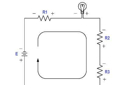
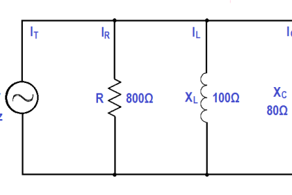
A 200 Ω resistor and a 50 Ω XL are placed in series with a voltage source, and the total current flow is 2 amps, as shown in Figure.

Calculate Power in Series RL Circuit

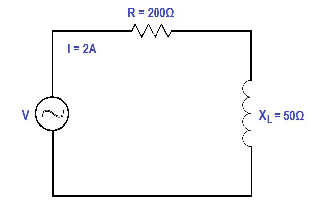
Figure : Series R-L Circuit

Find:

  1. Power Factor, pf
  2. Applied voltage, V
  3. True Power, P
  4. Reactive Power, Q
  5. Apparent Power, S

Solution:

1. Calculate Power factor (pf)
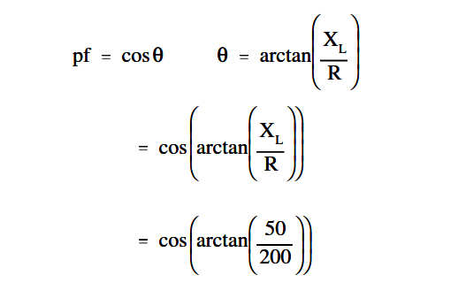
Calculate Power Factor

p.f. = cos (14º)

p.f. = 0.097

2. Calculate Applied Voltage, V

V = I Z

Z = √R2 + XL2

so, V = I√R2 + XL2

V = 2√2002 + 502

V = 2√42500

V = 2 x 206.16

V = 412.3 Volts

3. Calculate True Power, P

P = EI cos θ

P = (412.3)(2)(0.97)

P = 799.86 watts

4. Calculate Reactive Power, Q

Q = EI sin θ

Q = (412.3)(2)(0.242)

Q = 199.6 VAR

5. Calculate Apparent Power, S

S = EI

S = (412.3)(2)

S = 824.6 VA

Don't Miss Our Updates
Be the first to get exclusive content straight to your email.
We promise not to spam you. You can unsubscribe at any time.
Invalid email address
You've successfully subscribed !

Continue Reading

Types of Capacitors
Inductance and Inductive Reactance
Capacitance
Transformer Coil Polarity
AC Generator Nameplate Ratings
Capacitor
Share This Article
Facebook Whatsapp Whatsapp LinkedIn Copy Link
Share
Leave a Comment

Leave a Reply Cancel reply

Your email address will not be published. Required fields are marked *

Stay Connected

128.3kFollowersLike
69.1kFollowersFollow
210kSubscribersSubscribe
38kFollowersFollow

Categories

Explore More

Transformer Voltage Ratio
Inductive Time Constant
AC Generation
Synchronous Motors
Batteries Theory
Voltage Divider
Calculate Power in Series RC Circuit
Three Phase Wattmeter

Keep Learning

Resistor Y and Delta Network Calculation

Y and Delta Resistor Network Calculations

Carbon Atom

What is Electricity ?

DC Machine

DC Machines Construction

Armature Current in a DC Motor

DC Motor Torque

Left-Hand Rule for Generators

Starting of DC Motors

Electric Short Circuit

Series Short Circuit Faults

Air Circuit Breaker Principle

High Voltage Circuit Breaker Principle

Ammeter with Shunt

Ammeter

Learn More

Density Calculation​ Using DP Transmitter

How to Measure Density using DP Transmitter?

Selecting A Pneumatic Manifold

How to Select a Pneumatic Manifold

flow Nozzle

Flow Nozzle Principle, Advantages, Disadvantages, Applications

harmonics-effect-on-induction-motor

Harmonics effect on Induction Motor

Infrared Spectrometers Questions & Answers

Infrared Spectrometers Questions & Answers

Machine Indicator Lights PLC Programming Solution

Machine Indicator Lights: PLC Programming Solution

Energy Meter Data in PLC using Modbus Communication

Modbus Communication between PLC and Energy Meter

Formula for Linear mA to Square root mA conversion

Menu

  • About
  • Privacy Policy
  • Copyright

Quick Links

  • Learn PLC
  • Helping Hand
  • Part Time Job

YouTube Subscribe

Follow US
All rights reserved. Reproduction in whole or in part without written permission is prohibited.
Welcome Back!

Sign in to your account

Username or Email Address
Password

Lost your password?