AC motors are widely used to drive machinery for a wide variety of applications. To understand how these motors operate, a knowledge of the basic theory of operation of AC motors is necessary.
Principle of Operation
The principle of operation for all AC motors relies on the interaction of a revolving magnetic field created in the stator by AC current, with an opposing magnetic field either induced on the rotor or provided by a separate DC current source. The resulting interaction produces usable torque, which can be coupled to desired loads throughout the facility in a convenient manner. Prior to the discussion of specific types of AC motors, some common terms and principles must be introduced.
Rotating Field
Before discussing how a rotating magnetic field will cause a motor rotor to turn, we must first find out how a rotating magnetic field is produced. Figure 1 illustrates a three-phase stator to which a three-phase AC current is supplied.
The windings are connected in wye. The two windings in each phase are wound in the same direction. At any instant in time, the magnetic field generated by one particular phase will depend on the current through that phase. If the current through that phase is zero, the resulting magnetic field is zero. If the current is at a maximum value, the resulting field is at a maximum value. Since the currents in the three windings are 120° out of phase, the magnetic fields produced will also be 120° out of phase.
The three magnetic fields will combine to produce one field, which will act upon the rotor. In an AC induction motor, a magnetic field is induced in the rotor opposite in polarity of the magnetic field in the stator. Therefore, as the magnetic field rotates in the stator, the rotor also rotates to maintain its alignment with the stator’s magnetic field.
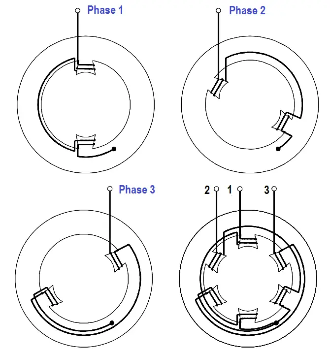
Figure 1 : Three-Phase Stator
From one instant to the next, the magnetic fields of each phase combine to produce a magnetic field whose position shifts through a certain angle. At the end of one cycle of alternating current, the magnetic field will have shifted through 360°, or one revolution (Figure 2). Since the rotor has an opposing magnetic field induced upon it, it will also rotate through one revolution.
For purpose of explanation, rotation of the magnetic field is developed in Figure 2 by “stopping” the field at six selected positions, or instances. These instances are marked off at 60° intervals on the sine waves representing the current flowing in the three phases, A, B, and C. For the following discussion, when the current flow in a phase is positive, the magnetic field will develop a north pole at the poles labeled A, B, and C. When the current flow in a phase is negative, the magnetic field will develop a north pole at the poles labeled A’, B’, and C’.
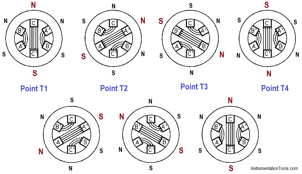
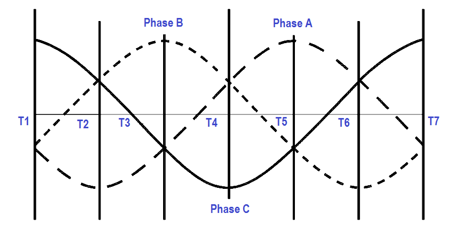
Figure 2 : Rotating Magnetic Field
At point T1, the current in phase C is at its maximum positive value. At the same instance, the currents in phases A and B are at half of the maximum negative value. The resulting magnetic field is established vertically downward, with the maximum field strength developed across the C phase, between pole C (north) and pole C’ (south). This magnetic field is aided by the weaker fields developed across phases A and B, with poles A’ and B’ being north poles and poles A and B being south poles.
At Point T2, the current sine waves have rotated through 60 electrical degrees. At this point, the current in phase A has increased to its maximum negative value. The current in phase B has reversed direction and is at half of the maximum positive value. Likewise, the current in phase C has decreased to half of the maximum positive value. The resulting magnetic field is established downward to the left, with the maximum field strength developed across the A phase, between poles A’ (north) and A (south). This magnetic field is aided by the weaker fields developed across phases B and C, with poles B and C being north poles and poles B’ and C’ being south poles. Thus, it can be seen that the magnetic field within the stator of the motor has physically rotated 60°.
At Point T3, the current sine waves have again rotated 60 electrical degrees from the previous point for a total rotation of 120 electrical degrees. At this point, the current in phase B has increased to its maximum positive value. The current in phase A has decreased to half of its maximum negative value, while the current in phase C has reversed direction and is at half of its maximum negative value also. The resulting magnetic field is established upward to the left, with the maximum field strength developed across phase B, between poles B (north) and B’ (south). This magnetic field is aided by the weaker fields developed across phases A and C, with poles A’ and C’ being north poles and poles A and C being south poles. Thus, it can be seen that the magnetic field on the stator has rotated another 60° for a total rotation of 120°.
At Point T4, the current sine waves have rotated 180 electrical degrees from Point T1 so that the relationship of the phase currents is identical to Point T1 except that the polarity has reversed. Since phase C is again at a maximum value, the resulting magnetic field developed across phase C will be of maximum field strength. However, with current flow reversed in phase C the magnetic field is established vertically upward between poles C’ (north) and C (south). As can be seen, the magnetic field has now physically rotated a total of 180° from the start.
At Point T5, phase A is at its maximum positive value, which establishes a magnetic field upward to the right. Again, the magnetic field has physically rotated 60° from the previous point for a total rotation of 240°.
At Point T6, phase B is at its maximum negative value, which will establish a magnetic field downward to the right. The magnetic field has again rotated 60° from Point T5 for a total rotation of 300°.
Finally, at Point T7, the current is returned to the same polarity and values as that of Point T1. Therefore, the magnetic field established at this instance will be identical to that established at Point T1.
From this discussion it can be seen that for one complete revolution of the electrical sine wave (360°), the magnetic field developed in the stator of a motor has also rotated one complete revolution (360°). Thus, you can see that by applying three-phase AC to three windings symmetrically spaced around a stator, a rotating magnetic field is generated.
Torque Production
When alternating current is applied to the stator windings of an AC induction motor, a rotating magnetic field is developed. The rotating magnetic field cuts the bars of the rotor and induces a current in them due to generator action. The direction of this current flow can be found using the left-hand rule for generators.
This induced current will produce a magnetic field, opposite in polarity of the stator field, around the conductors of the rotor, which will try to line up with the magnetic field of the stator. Since the stator field is rotating continuously, the rotor cannot line up with, or lock onto, the stator field and, therefore, must follow behind it (Figure 3).
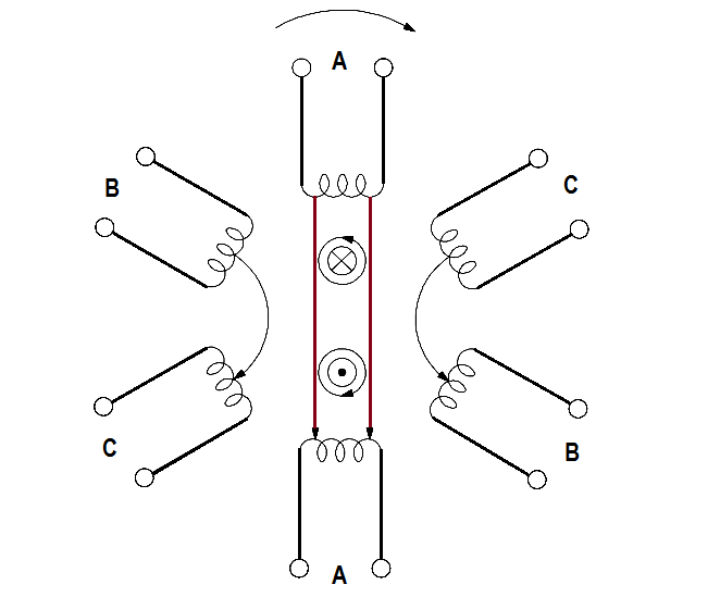
Figure 3 : Induction Motor