Inst ToolsInst ToolsInst Tools
  • Courses
  • Automation
    • PLC
    • Control System
    • Safety System
    • Communication
    • Fire & Gas System
  • Instrumentation
    • Design
    • Pressure
    • Temperature
    • Flow
    • Level
    • Vibration
    • Analyzer
    • Control Valve
    • Switch
    • Calibration
    • Erection & Commissioning
  • Interview
    • Instrumentation
    • Electrical
    • Electronics
    • Practical
  • Q&A
    • Instrumentation
    • Control System
    • Electrical
    • Electronics
    • Analog Electronics
    • Digital Electronics
    • Power Electronics
    • Microprocessor
  • Request
Search
  • Books
  • Software
  • Projects
  • Process
  • Tools
  • Basics
  • Formula
  • Power Plant
  • Root Cause Analysis
  • Electrical Basics
  • Animation
  • Standards
  • 4-20 mA Course
  • Siemens PLC Course
Reading: Level Transmitter Calibration Procedure
Share
Notification Show More
Font ResizerAa
Inst ToolsInst Tools
Font ResizerAa
  • Courses
  • Design
  • PLC
  • Interview
  • Control System
Search
  • Courses
  • Automation
    • PLC
    • Control System
    • Safety System
    • Communication
    • Fire & Gas System
  • Instrumentation
    • Design
    • Pressure
    • Temperature
    • Flow
    • Level
    • Vibration
    • Analyzer
    • Control Valve
    • Switch
    • Calibration
    • Erection & Commissioning
  • Interview
    • Instrumentation
    • Electrical
    • Electronics
    • Practical
  • Q&A
    • Instrumentation
    • Control System
    • Electrical
    • Electronics
    • Analog Electronics
    • Digital Electronics
    • Power Electronics
    • Microprocessor
  • Request
Follow US
All rights reserved. Reproduction in whole or in part without written permission is prohibited.
Inst Tools > Blog > Calibration > Level Transmitter Calibration Procedure

Level Transmitter Calibration Procedure

Last updated: May 27, 2019 4:23 pm
Editorial Staff
Calibration Level Measurement
5 Comments
Share
2 Min Read
SHARE

Calibration Procedure

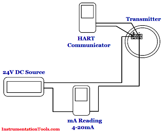
  1. Set up the guided wave radar level transmitter, HART communicator, power supply, and the multimeter as below (see below calibration setup Diagram).
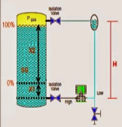
  2. Check the configuration of the lower range value (0% level, 4 mA) and high range value (100% level, 20 mA). Make sure that the inputted data is as per datasheet. For example, the lower range value is 10 inch and the high range value is 35 inch (both of it are measured from the bottom of level transmitter probe)
  3. Fill the level transmitter chamber with water up to the 0% level. Read the level measurement in the transmitter LCD (or in the HART communicator). Set this condition as 0% level through HART communicator.
  4. Read the mA output of the transmitter by using a multimeter. Adjust (if any) through the HART communicator so that the output of the transmitter (on multimeter) is 4 mA.
  5. Fill the level transmitter chamber with water up to the 100% level. Read the level measurement in the transmitter LCD (or in the HART communicator). Set this condition as 100% level through HART communicator.
  6. Read the mA output of the transmitter by using a multimeter. Adjust (if any) through the HART communicator so that the output of the transmitter (on multimeter) is 20 mA.

Calibration Setup Diagram :

level-transmitter-calibration-procedure

Typical tools required:

  1. 24 VDC power supply
  2. Multimeter digital
  3. Water Supply Connection
  4. HART communicator
  5. Screwdriver set
  6. Wrench set

Note:

point number 1, 2, and 4 of the typical tools above can be replaced by a single multifunction calibrator available in the market. This typical maintenance procedure is just an illustration of how to regularly service a guided wave radar level transmitter for academic purpose only. This typical procedure shall not be used as day to day operation guidance. The vendor specific maintenance manual shall be used in detail.

Don't Miss Our Updates
Be the first to get exclusive content straight to your email.
We promise not to spam you. You can unsubscribe at any time.
Invalid email address
You've successfully subscribed !

Continue Reading

Why it is important to note As-Found and As-Left data during Calibration?
The 5 ways Ultrasonic Sensors Work
DP Level Transmitter Calibration for Diaphragm Seal with Capillary
Open Tank Level Measurement using DP Transmitters Animation
Contact Type Guided Wave Radar Level Transmitter Working Principle
Level Measurement with Wet leg and Installed Below Tapping Point
Share This Article
Facebook Whatsapp Whatsapp LinkedIn Copy Link
Share
5 Comments
  • Stephen Salomane says:
    December 20, 2016 at 5:14 am

    Basic knowledge… very useful.

    Reply
  • Md Mehebub says:
    January 25, 2017 at 12:53 pm

    Thanks….

    Reply
  • bhagwan singh lodha says:
    March 5, 2020 at 6:18 pm

    If the transmitter zero and span are mismatching so what’s the procedure of the calibration.and zero trim.

    Reply
  • Mathias udoudo says:
    March 6, 2020 at 11:26 am

    Good

    Reply
  • abdelwaheb bedoui says:
    February 12, 2024 at 3:15 pm

    Dear Sir,
    Actually we Have new level transmitter’s Resmount 5300 Serie installed in the field,
    next time AS we will proceed to start them, I want to now the reference of Hart communicator for calibration these new level Transmitter’s.
    Thanks to Answer me ASAP, to proceed for purchase.
    Best Regards,

    Reply

Leave a Reply Cancel reply

Your email address will not be published. Required fields are marked *

Stay Connected

128.3kFollowersLike
69.1kFollowersFollow
210kSubscribersSubscribe
38kFollowersFollow

Categories

Explore More

Open Tank DP Level Transmitter Calculations
Pressure Safety Valves Functional Testing
Tilt Level Switch Working Animation
RF Level Switches Working Principle
Calibration of Weight using the ABBA Method
Displacer (buoyancy) Level Transmitter Principle, Limitations, Design, Installation & Calibration
Pressure Gauge Functional Testing
Closed tank DP Level Transmitter with wet leg elevation zero direct mount Calibration

Keep Learning

Sounding Level Transmitter Working Animation

Which instrument is at fault in this system

Which Instrument is at Fault in this System?

Instruments Tapping Points

Instruments Tapping Points – Common versus Individual

DP Transmitters Level Measurement Principle

DP Transmitters Level Measurement Principle Video

Weighing Balance Calibration

Calibration Procedure of Weighing Balance and Common Mistakes

Fieldbus Flow Transmitter Calibration

Foundation Fieldbus Transmitter Calibration

Selection of Weighing Balance

Selection of Weighing Balance and Weight for Calibration

Radar and Ultrasonic Level Transmitter Problems Troubleshooting

Radar and Ultrasonic Level Transmitter Practical Problems Troubleshooting

Learn More

Electrical Machines Questions and Answers

Inductive Impedance Questions

Moisture Separator

Inhouse Moisture separator for Pneumatic Systems

What is Gas Chromatography

What is Gas Chromatography?

Logic for Always ON and Always OFF bit

Always ON and OFF Bit using Ladder Logic and Statement List

Electrical and Instrumentation Engineering Documents

Electrical and Instrumentation – Automation Pre-engineering Documents

DP-Level-Transmitter-Open-tank-calibration

Open Tank DP Level Transmitter Calibration

Capacitance Level measurement principle

Capacitance Level Sensor Principle, Limitations, Installation & Calibration

How Could FB and FC Make Me Professional PLC Programmer

How Could FB and FC Make Me Professional PLC Programmer?

Menu

  • About
  • Privacy Policy
  • Copyright

Quick Links

  • Learn PLC
  • Helping Hand
  • Part Time Job

YouTube Subscribe

Follow US
All rights reserved. Reproduction in whole or in part without written permission is prohibited.
Welcome Back!

Sign in to your account

Username or Email Address
Password

Lost your password?