Inst ToolsInst ToolsInst Tools
  • Courses
  • Automation
    • PLC
    • Control System
    • Safety System
    • Communication
    • Fire & Gas System
  • Instrumentation
    • Design
    • Pressure
    • Temperature
    • Flow
    • Level
    • Vibration
    • Analyzer
    • Control Valve
    • Switch
    • Calibration
    • Erection & Commissioning
  • Interview
    • Instrumentation
    • Electrical
    • Electronics
    • Practical
  • Q&A
    • Instrumentation
    • Control System
    • Electrical
    • Electronics
    • Analog Electronics
    • Digital Electronics
    • Power Electronics
    • Microprocessor
  • Request
Search
  • Books
  • Software
  • Projects
  • Process
  • Tools
  • Basics
  • Formula
  • Power Plant
  • Root Cause Analysis
  • Electrical Basics
  • Animation
  • Standards
  • 4-20 mA Course
  • Siemens PLC Course
Reading: PLC Energize or De-energize the Outputs based on Events
Share
Font ResizerAa
Inst ToolsInst Tools
Font ResizerAa
  • Courses
  • Design
  • PLC
  • Interview
  • Control System
Search
  • Courses
  • Automation
    • PLC
    • Control System
    • Safety System
    • Communication
    • Fire & Gas System
  • Instrumentation
    • Design
    • Pressure
    • Temperature
    • Flow
    • Level
    • Vibration
    • Analyzer
    • Control Valve
    • Switch
    • Calibration
    • Erection & Commissioning
  • Interview
    • Instrumentation
    • Electrical
    • Electronics
    • Practical
  • Q&A
    • Instrumentation
    • Control System
    • Electrical
    • Electronics
    • Analog Electronics
    • Digital Electronics
    • Power Electronics
    • Microprocessor
  • Request
Follow US
All rights reserved. Reproduction in whole or in part without written permission is prohibited.
Inst Tools > Blog > PLC Tutorials > PLC Energize or De-energize the Outputs based on Events

PLC Energize or De-energize the Outputs based on Events

Write a PLC Program to Energize or De-energize the Outputs based on Events using PLC programming ladder logic. plc programs for practice.

Last updated: November 2, 2023 4:58 pm
Editorial Staff
PLC Tutorials
3 Comments
Share
2 Min Read
SHARE

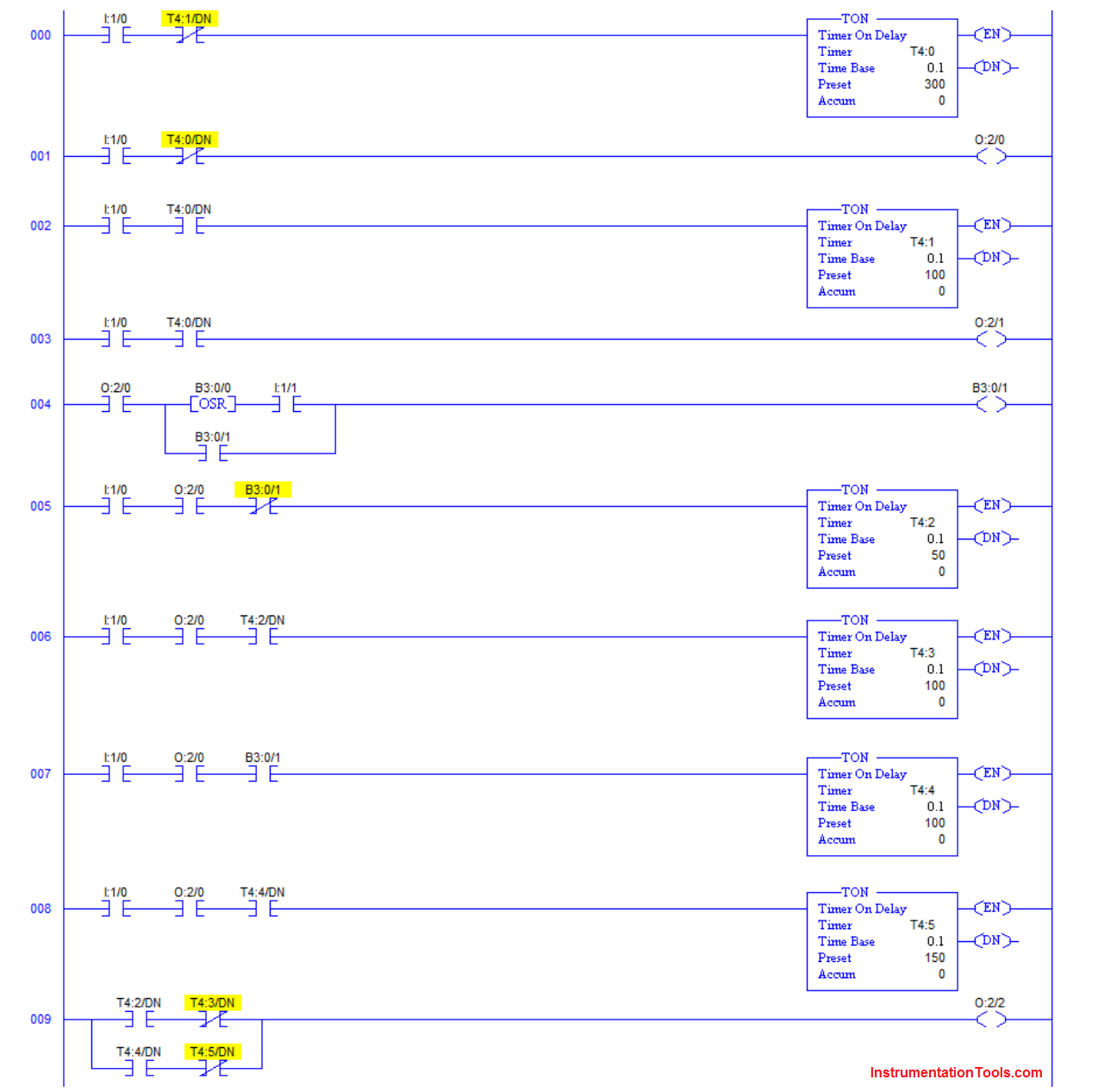
Write the following PLC Program to Energize or De-energize the Outputs based on Events.

A certain switch (I:1/0) is to start a process.

The process is to run for 30 seconds, stop for 10 seconds and then repeat as long switch I:1/0 remains closed.

Opening I:1/0 at any time is to reset all timers and de-energize all outputs. Output O:2/0 is to be energized during the 30s run period and output O:2/1 is to be energized during the 10s stop period.

During the run period, a single output O:2/2 is controlled by input I:1/1. If I:1/1 is open (at the beginning of the run period) O:2/2 is to be off for the first 5 seconds then on for 10 seconds.

If I:1/1 is closed (at the beginning of the run period) O:2/2 is to be off for the first 10 seconds then on for 15 seconds.

Changing I:1/1 after the run period has begun should not change the above sequence. Output O:2/2 is always to be off during the stop period.

PLC Energize or De-energize Outputs

PLC Energize or De-energize Outputs

You can share the detailed explanation of above PLC ladder logic with comments section.

Author: Dr. D. J. Jackson

If you liked this article, then please subscribe to our YouTube Channel for PLC and SCADA video tutorials.

You can also follow us on Facebook and Twitter to receive daily updates.

Read Next:

  • PLC Program to Read Temperature in PLC
  • PID Controller Parameters Tuning Manually
  • PLC Program for Daily Production Record
  • Programmable Logic Controller Questions
  • Control Valves Application using PLC
Don't Miss Our Updates
Be the first to get exclusive content straight to your email.
We promise not to spam you. You can unsubscribe at any time.
Invalid email address
You've successfully subscribed !

Continue Reading

Monitor and Modify Variables in Simatic Manager
Free SCADA Training Course
Alarm Acknowledge using PLC
Difference between PLC and Computers
Best 100 PLC Projects for Final Year Engineering Students
PLC Program for Solenoid, Pilot Lamp, and Switch with Alarm
Share This Article
Facebook Whatsapp Whatsapp LinkedIn Copy Link
Share
3 Comments
  • Vijay Raghuwanshi says:
    July 5, 2019 at 11:47 pm

    Which software you used

    Reply
  • Tsepo Rasilalume says:
    July 25, 2022 at 1:15 pm

    Hi, exactly what I’ve been searching for – Thanks.
    Is it possible to write it in STL? I struggle a bit with Ladder.

    Many Thanks.
    Tsepo

    Reply
  • Million Haile says:
    July 6, 2023 at 1:04 am

    Hi.my name Million Haile.can you show me ladder diagram for bar soap wrapping machine

    Reply

Leave a Reply Cancel reply

Your email address will not be published. Required fields are marked *

Stay Connected

128.3kFollowersLike
69.1kFollowersFollow
210kSubscribersSubscribe
38kFollowersFollow

Categories

Explore More

PLC Techniques for I/O Mapping
PLC Example to Control LEDs Via Switches
Instrumentation System Architecture
PLC Analog Signals Wiring Techniques
PLC Motor Operation based on Time Cycle Sequence – Program
Top PLC Manufacturers
Overview of SIEMENS PLC – S7-1500, S7-1200, S7-400, S7-300
Medium-Level PLC Exercise for Students in Automation

Keep Learning

memory types in siemens plc

Memory Structure of Siemens PLC

Smart Drip Irrigation System Using PLC

Scheduled Daily Plant Watering PLC Program

PLC Program for Sequential Motor Control

PLC Program for Sequential Motor Control

Siemens PLC motor direction control example

Siemens TIA Portal: Motor Forward Reverse PLC Logic

Top 100 PLC Objective Questions and Answers

Top 100 PLC Objective Questions and Answers

Firmware Version in Siemens PLC

What is the Firmware Version of a PLC? – Siemens PLC Hardware

Lamp Counter Logic

Function Block (FB) for Motor Control Logic

Types of Allen Bradley PLC

Types of Allen Bradley PLC

Learn More

nuclear magnetic resonance (NMR) spectroscopy

Pharmaceutical Industry: The Role of Precision Tools

Self-actuated Temperature Regulator

Self-actuated Temperature Regulator – Principle, Types, Advantages

Alternate 110 KV Connection to Feeder A

Alternate 110 KV Connection to Feeder A

Structured Text Automatic Gate Logic

Structured Text PLC Programming for Automatic Gate Control

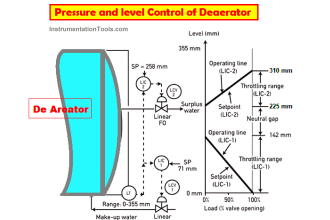
Deaerator Pressure and Level Control System in Power Plants

Deaerator Pressure and Level Control System in Power Plants

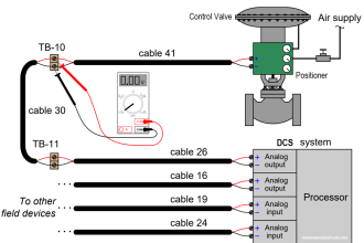
DCS Troubleshooting Control Valve Loop

DCS Troubleshooting Control Valve Loop

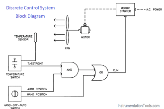
Discrete control system block diagram

Process Control Instrumentation

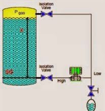
Closed-tank-DP-Level-Transmitter-with-cleaning-leg-Calibration

Closed tank DP Level Transmitter with cleaning leg Calibration

Menu

  • About
  • Privacy Policy
  • Copyright

Quick Links

  • Learn PLC
  • Helping Hand
  • Part Time Job

YouTube Subscribe

Follow US
All rights reserved. Reproduction in whole or in part without written permission is prohibited.
Welcome Back!

Sign in to your account

Username or Email Address
Password

Lost your password?