Inst ToolsInst ToolsInst Tools
  • Courses
  • Automation
    • PLC
    • Control System
    • Safety System
    • Communication
    • Fire & Gas System
  • Instrumentation
    • Design
    • Pressure
    • Temperature
    • Flow
    • Level
    • Vibration
    • Analyzer
    • Control Valve
    • Switch
    • Calibration
    • Erection & Commissioning
  • Interview
    • Instrumentation
    • Electrical
    • Electronics
    • Practical
  • Q&A
    • Instrumentation
    • Control System
    • Electrical
    • Electronics
    • Analog Electronics
    • Digital Electronics
    • Power Electronics
    • Microprocessor
  • Request
Search
  • Books
  • Software
  • Projects
  • Process
  • Tools
  • Basics
  • Formula
  • Power Plant
  • Root Cause Analysis
  • Electrical Basics
  • Animation
  • Standards
  • 4-20 mA Course
  • Siemens PLC Course
Reading: What is a Bus Coupler in Electrical Panel?
Share
Notification Show More
Font ResizerAa
Inst ToolsInst Tools
Font ResizerAa
  • Courses
  • Design
  • PLC
  • Interview
  • Control System
Search
  • Courses
  • Automation
    • PLC
    • Control System
    • Safety System
    • Communication
    • Fire & Gas System
  • Instrumentation
    • Design
    • Pressure
    • Temperature
    • Flow
    • Level
    • Vibration
    • Analyzer
    • Control Valve
    • Switch
    • Calibration
    • Erection & Commissioning
  • Interview
    • Instrumentation
    • Electrical
    • Electronics
    • Practical
  • Q&A
    • Instrumentation
    • Control System
    • Electrical
    • Electronics
    • Analog Electronics
    • Digital Electronics
    • Power Electronics
    • Microprocessor
  • Request
Follow US
All rights reserved. Reproduction in whole or in part without written permission is prohibited.
Inst Tools > Blog > Electrical Basics > What is a Bus Coupler in Electrical Panel?

What is a Bus Coupler in Electrical Panel?

Bus-coupler is one of the most important components used in an electrical panel. In this post, we will learn the concept of a bus coupler.

Last updated: January 9, 2023 2:13 pm
Viral Nagda
Electrical Basics
No Comments
Share
4 Min Read
SHARE

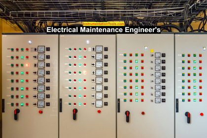
An electrical panel consists of many electrical components which must be understood properly for correct working. In electrical panels, you must have seen red, yellow, and blue color plates which are used in many distributed applications. This is called a bus coupler.

Bus-coupler is one of the most important components used in an electrical panel. In this post, we will learn the concept of a bus coupler.

What is a Bus coupler?

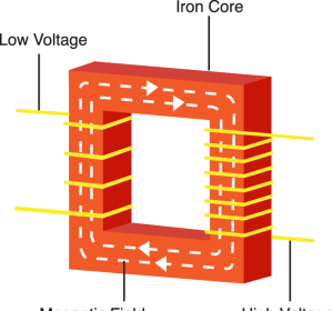
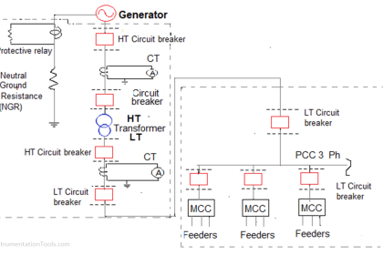
First of all, let us understand what a bus bar is. A bus bar can be said as a group of conductor plates (three phases of R, Y, and B) that gets the main incoming power and distributes it to various outgoing requirements.

Refer to the below image for understanding. The main incoming three-phase supply is fed to the three plates of conductors. From these plates, various other small plates are distributed to panels or feeders which require three phase supply.

What is a Bus Coupler in Electrical Panel

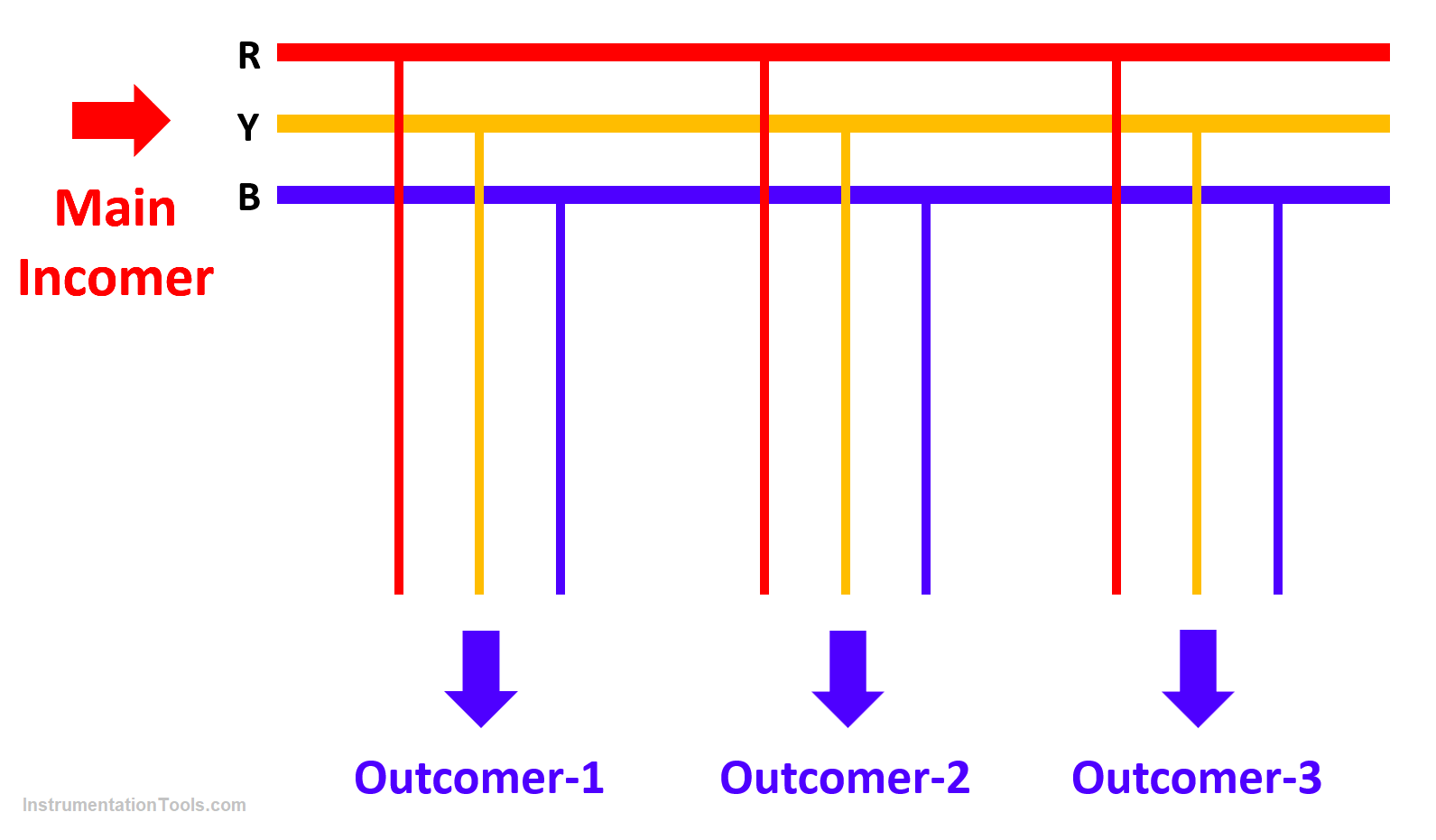
What happens is that you get a uniform connection and avoid a large number of connections to the main incomer. You have only one incoming supply and you can get multiple outgoing connections to various feeders which require supply.

Let us move ahead to the bus coupler now. Suppose there are two bus-bar panels. One panel is used to take incoming supply from transformer-1 and another panel is used to take supply from transformer-2.

Both these bus-bars are providing supply to the load. Now, comes the role of a bus coupler. Bus-coupler is a component that combines multiple bus bars together.

There are two uses for it. Let us see the first case. The bus coupler can be used to provide supply from the first bus bar by default. In case it fails, then it will cut off the first one and take the supply from the second one.

Here, the load will remain disconnected for some time. In this case, the two bus bars will be isolated from each other through the bus coupler.

Let us now take the second case. The bus coupler will connect both bus bars simultaneously. In case the first bus bar fails, then the load will be connected through the second bus bar. It will not stop consuming current even for a second. Thus, in any case, you can see that the bus coupler is used to combine multiple bus bars together.

So, the concept of a bus coupler is simple. It can either be used to connect multiple bus bars at a time simultaneously or connect them only one at a time; depending upon the current consumption and the amount of time the load can withstand disconnection of power.

In this way, we understand the concept of a bus coupler in an electrical panel.

If you liked this article, then please subscribe to our YouTube Channel for Electrical, Electronics, Instrumentation, PLC, and SCADA video tutorials.

You can also follow us on Facebook and Twitter to receive daily updates.

Read Next:

  • Electrical Drawings
  • Motor Cooling Methods
  • SCADA in Power System
  • What is a Buchholz Relay?
  • Cables between VFD & Motor
Don't Miss Our Updates
Be the first to get exclusive content straight to your email.
We promise not to spam you. You can unsubscribe at any time.
Invalid email address
You've successfully subscribed !

Continue Reading

Why is Phase Failure Relay Required in LV Panels?
Electrical Cabinet Air Conditioner – Enclosure Cooling, Maintenance
What is an HRC Fuse? – Material, Types, Advantages
What is a Relay? Types of Industrial Relays
VFD Pros and Cons – Variable Frequency Drives
What is insulation? How to Choose the Insulation Material?
Share This Article
Facebook Whatsapp Whatsapp LinkedIn Copy Link
Share
Leave a Comment

Leave a Reply Cancel reply

Your email address will not be published. Required fields are marked *

Stay Connected

128.3kFollowersLike
69.1kFollowersFollow
210kSubscribersSubscribe
38kFollowersFollow

Categories

Explore More

What is a Protective Relay? Principle, Advantages, Applications
Comparison of Electrical Protection Relays
Electrical Switches Principle & Types
Why is IGBT used in VFD?
Electric Motors Efficiency Classes
Motor Control Center – Purpose, Classification, and Advantages
What is Torque Boosting in Variable Frequency Drive (VFD)?
Contactor – Basics, Wiring, Connection with PLC

Keep Learning

Difference between Servo Motor and DC Motor

Difference between Servo Motor and DC Motor

Electrical Maintenance Engineer's Biggest Enemy

Electrical Components Overheating – Causes, Troubles, Prevent

Differences between Watts and Volt Amps

Differences between Watts and Volt Amps

What is electrical transformer

Basics of Electrical Transformer

How to Read and Understand an Electrical Single Line Diagram?

How to Read and Understand an Electrical Single Line Diagram?

Why is Motor Control Required in Control Systems

Why is Motor Control Required in Control Systems?

Earth Fault

What are Ground Fault and Earth Fault?

Relay Parts

NO vs NC Contact

Learn More

Online time of the PLC

System and Local Time in PLC

OB and FB Blocks in Siemens PLC

Procedure for Siemens S7-300 Download from PC to PLC

Measurement of Carbon Dioxide in Flue Gas

Measurement of Carbon Dioxide in Flue Gas

Retentive ON delay timer using PLC Logic

Retentive ON Delay Timer using PLC

Automation Engineers Interview Questions

Industrial Automation Engineers Interview Questions

stepper motors Animation

Fundamentals of DC Motor Animation

Geothermal Air Conditioners

Types of Air Conditioning Systems

Computer Science and Technology Certifications

Computer Science and Technology Majors Certifications

Menu

  • About
  • Privacy Policy
  • Copyright

Quick Links

  • Learn PLC
  • Helping Hand
  • Part Time Job

YouTube Subscribe

Follow US
All rights reserved. Reproduction in whole or in part without written permission is prohibited.
Welcome Back!

Sign in to your account

Username or Email Address
Password

Lost your password?