PLC programming has five types of languages in it. They are ladder logic, structured text, functional block diagram, sequential flow chart, and instruction list. Every programmer designs the logic according to its need and comfort level in understanding.
PLC Basics
One of the oldest PLC languages is ladder logic. When electrical relay controls were started to be replaced with PLC panels, it was found that the ladder logic resemblance was very similar to an electrical drawing.
This helped the PLC programmers in easily interpreting them. Ladder logic is still used by many programmers for logic development. In this post, we will compare ladder logic with other PLC programming languages.
Ladder Logic
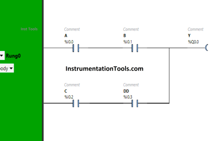
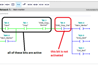
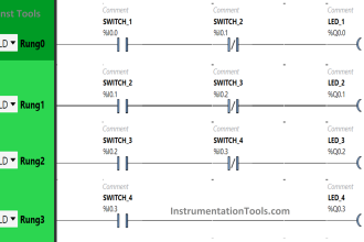
Ladder logic is one of the most common and used languages in the PLC program. As the name defines, this language is written in a ladder-type way. Refer to the below image for understanding. As you can see, it is a series of rungs, numbered from one to n number. You can write logic in each of these rungs.
When the PLC program is executed in the CPU, the flow starts from top to bottom. This means the first rung is executed first and then the last rung, and then the cycle repeats. In each rung, the left-hand part is the input side and the right-hand part is the output side. When you see the logic online in animation, you will find that each element in the rung gets colored as on or off, or the numeric value is shown.
This helps the programmer easily identify the logic. So, you can see that ladder logic is quite a simple way to write the program. But, you can write this same program in other languages too. It depends on the programmer and his understanding. Let us have a look at each of them and understand what the difference between them is.
Ladder Logic vs. Structured Text
Structured text is a language in which the logic is written in text format, similar to software languages used in IT. The logic flow is the same as written in ladder logic, but the style of writing is different. Structured text (ST) language directly uses mnemonics, like AND, OR, NOT, IF, ELSE, etc. This means the way we write the logic in NO and NC format in either series or parallel way; the same is denoted in text format way.
Refer to the below figure for an example. Let us interpret the first rung written in ladder logic with that written in ST. If IP_AM_SEL is off, and IP_OP_ON is on and IP_A_SLOW_IP is off, then IP_A_SV value will be moved to OP_SV. This interpretation is written in ST as shown in the figure. The meaning is the same, only the way of conveying is different.
ST language is useful when you have complex mathematical calculations and this makes programming look very easy. Structured Text is also better for looping over sections of logic since it has built-in instructions like FOR and WHILE which are designed for looping.
In the Ladder Diagram, you have to build loop constructs yourself. But, in terms of simplicity, ladder logic is far easier; because it is visually easy to look in online mode and also makes debugging comfortable. In ST, you have to scan and understand lining properly for debugging.
Ladder Logic vs. Functional Block Diagram
The functional block diagram is a language in which the logic is written in block format. The logic flow is the same as written in ladder logic, but the style of writing is different. The functional block diagram (FBD) language directly uses blocks, like AND, OR, NOT, MOVE, etc. The blocks are connected with each other via links. This means the way we write the logic in NO and NC format in either series or parallel way; the same is denoted in block format way.
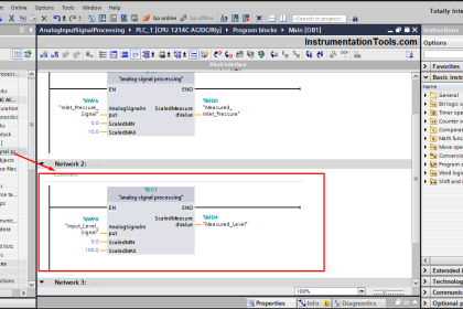
Refer to the below figure for an example. Let us interpret the first rung written in ladder logic with that written in FBD. If IP_AM_SEL is off, and IP_OP_ON is on and IP_A_SLOW_IP is off, then IP_A_SV value will be moved to OP_SV. This interpretation is written in FBD as shown in the figure. The meaning is the same, only the way of conveying is different.
FBD language is the easiest language to use for troubleshooting. This is because in one window only, you get to see many elements for visualization, as compared to ladder logic where you need to scroll up and down every time for debugging. FBD is commonly used in the process industry because its appearance is similar to P&IDs that define how process equipment is laid out.
Ladder Logic vs Sequential Flow Chart
The sequential flow chart is a language in which the logic is written in flowchart format. The logic flow is the same as written in ladder logic, but the style of writing is different. The sequential flow chart (SFC) language directly uses actions, transitions, steps, conditions, branches, and macros. The blocks are connected with each other via a flow chart way. This means the way we write the logic in NO and NC format in either series or parallel way; the same is denoted in flow chart way.
Refer to the below figure for an example. Let us interpret the first rung written in ladder logic with that written in SFC. If IN 1 is on, then OUT1 turns on. In the next step, if OUT 1 is on and if IN 2 is on, then OUT2 turns on. This interpretation is written in SFC as shown in the figure with the way of steps. The meaning is the same, only the way of conveying is different.
SFC language is not possible for smaller applications. For that, ladder logic is the best one used. Because you need to carefully design actions and processes in a proper flow chart way, using it for smaller control logic will waste time as well as make the logic more difficult to look at. Also, a large amount of space is consumed in making the logic. So, SFC must be used for complex and bigger applications and not smaller ones.
Ladder Logic vs. Instruction List
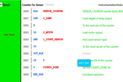
Instruction List is a language in which the logic is written in text format, but similar to assembly-type languages. The logic flow is the same as written in ladder logic, but the style of writing is different. Instruction List (IL) language directly uses assembly language texts, like AND, ANDN, LDN, etc. The language is a mix of ladder logic and structured text. This means the way we write the logic in NO and NC format in either series or parallel way; the same is denoted in assembly text format way.
Refer to the below figure for an example. Let us interpret the first rung written in ladder logic with that written in IL. If %M0 is off, and %M1 is on and %M2 is off, then the 2 value will be moved to %MW0. This interpretation is written in IL as shown in the figure. The meaning is the same, only the way of conveying is different.
Usually, it is the least used language, due to it’s complex writing methods and interpretations. So, the preferred language is ladder logic in this case.
Comparison
| Description | Ladder Logic | Structured Text | Functional Block Diagram | Sequential Flow Chart | Instruction List |
|---|---|---|---|---|---|
| Standardization | IEC 61131-3 | IEC 61131-3 | IEC 61131-3 | IEC 61131-3 | IEC 61131-3 |
| Complexity | Low to Medium | Medium to High | Low to Medium | Medium to High | Medium to High |
| Learning Curve | Easy | Moderate | Easy | Moderate | Difficult |
| Representation | Graphical | Text-based | Graphical | Graphical | Text-based |
| Best Suited For | Relay Logic Circuits and Process Control | Complex Algorithms | Process Control | Complex Sequencing | Low-level Operations |
| Code Reusability | Moderate | High | High | High | Low |
| Flexibility | Moderate | High | High | High | Low |
| Debugging | Easier due to graphical nature | Requires syntax knowledge | Easier due to graphical nature | Requires logical flow analysis | Difficult due to text-based nature |
| Execution Speed | Moderate | Fast | Moderate | Moderate | Fast |
In this way, we saw the comparison of ladder logic and other programming languages.
If you liked this article, then please subscribe to our YouTube Channel for Instrumentation, Electrical, PLC, and SCADA video tutorials.
You can also follow us on Facebook and Twitter to receive daily updates.
Read Next:
- Faceplate Design in PLC HMI
- PLC Memory Organization
- DCS, RTU, SCADA, and PAC
- Counters in PLC Programming
- PLC Product Sorting Machine