Inst ToolsInst ToolsInst Tools
  • Courses
  • Automation
    • PLC
    • Control System
    • Safety System
    • Communication
    • Fire & Gas System
  • Instrumentation
    • Design
    • Pressure
    • Temperature
    • Flow
    • Level
    • Vibration
    • Analyzer
    • Control Valve
    • Switch
    • Calibration
    • Erection & Commissioning
  • Interview
    • Instrumentation
    • Electrical
    • Electronics
    • Practical
  • Q&A
    • Instrumentation
    • Control System
    • Electrical
    • Electronics
    • Analog Electronics
    • Digital Electronics
    • Power Electronics
    • Microprocessor
  • Request
Search
  • Books
  • Software
  • Projects
  • Process
  • Tools
  • Basics
  • Formula
  • Power Plant
  • Root Cause Analysis
  • Electrical Basics
  • Animation
  • Standards
  • 4-20 mA Course
  • Siemens PLC Course
Reading: Guided-Wave Radar Instruments Diagnostics
Share
Font ResizerAa
Inst ToolsInst Tools
Font ResizerAa
  • Courses
  • Design
  • PLC
  • Interview
  • Control System
Search
  • Courses
  • Automation
    • PLC
    • Control System
    • Safety System
    • Communication
    • Fire & Gas System
  • Instrumentation
    • Design
    • Pressure
    • Temperature
    • Flow
    • Level
    • Vibration
    • Analyzer
    • Control Valve
    • Switch
    • Calibration
    • Erection & Commissioning
  • Interview
    • Instrumentation
    • Electrical
    • Electronics
    • Practical
  • Q&A
    • Instrumentation
    • Control System
    • Electrical
    • Electronics
    • Analog Electronics
    • Digital Electronics
    • Power Electronics
    • Microprocessor
  • Request
Follow US
All rights reserved. Reproduction in whole or in part without written permission is prohibited.
Inst Tools > Blog > Level Measurement > Guided-Wave Radar Instruments Diagnostics

Guided-Wave Radar Instruments Diagnostics

Last updated: May 24, 2019 5:17 pm
Editorial Staff
Level Measurement
No Comments
Share
6 Min Read
SHARE

Modern radar level instruments provide a wealth of diagnostic information to aid in troubleshooting.

One of the most informative is the echo curve, showing each reflected signal received by the instrument along the incident signal’s path of travel.

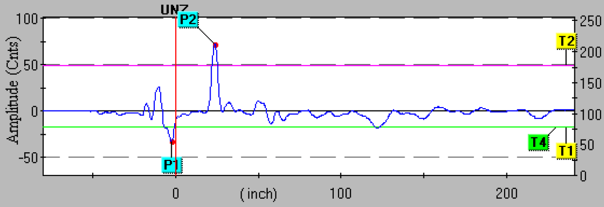
The following image is a screen capture of a computer display, from software used to configure a Rosemount model 3301 guided-wave radar level transmitter with a coaxial probe:

guided-wave radar Transmitter Diagnostics

To view a animation showing how a guided-wave radar (GWR) instrument detects both liquid surface level and liquid-liquid interface level, CLICK HERE

Pulse P1 is the reference or fiducial pulse, resulting from the change in dielectric permittivity between the extended “neck” of the probe (connecting the transmitter to the probe tube) and the coaxial probe itself. This pulse marks the top of the probe, thereby establishing a point of reference for ullage measurement.

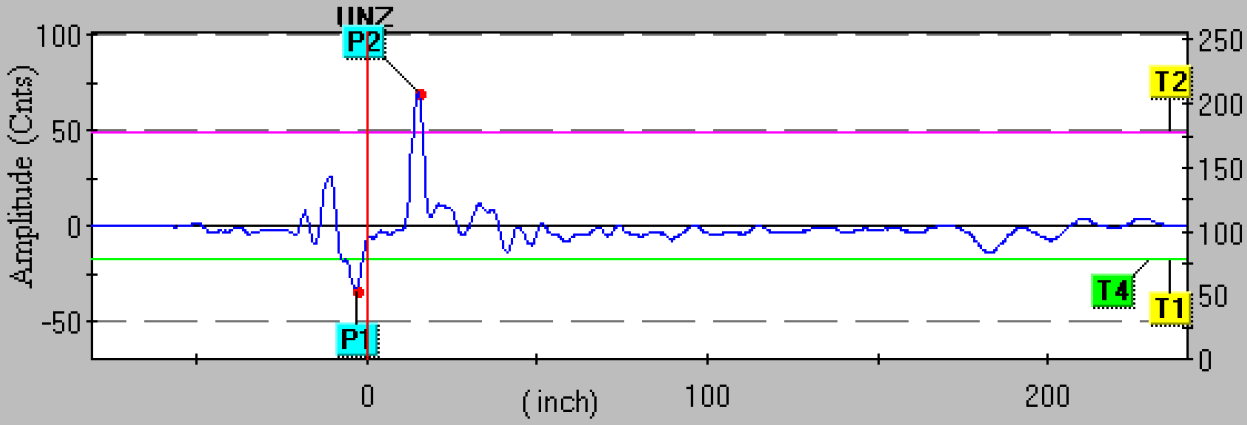
This next screen capture shows the same level transmitter measuring a water level that is 8 inches higher than before. Note how pulse P2 is further to the left (indicating an echo received sooner in time), indicating a lesser ullage (greater level) measurement:

guided-wave radar Transmitter Troubleshooting

Several threshold settings determine how the transmitter categorizes each received pulse. Threshold T1 for this particular radar instrument defines which pulse is the reference (fiducial).

Thus, the first echo in time to exceed the value of threshold T1 is interpreted by the instrument to be the reference point. Threshold T2 defines the upper product level, so the first echo in time to exceed this threshold value is interpreted as the vapor/liquid interface point. Threshold T3 for this particular transmitter is used to define the echo generated by a liquid-liquid interface.

However, threshold T3 does not appear in this echo plot because the interface measurement option was disabled during this experiment.

The last threshold, T4, defines the end-of-probe detection. Set at a negative value (just like the reference threshold T1), threshold T4 looks for the first pulse in time to exceed that value and interprets that pulse as the one resulting from the signal reaching the probe’s end.

All along the echo curve you can see weak echo signals showing up as bumps. These echoes may be caused by discontinuities along the probe (solid deposits, vent holes, centering spacers, etc.), discontinuities in the process liquid (suspended solids, emulsions, etc.), or even discontinuities in the surrounding process vessel (for non-coaxial probes which exhibit varying degrees of sensitivity to surrounding objects).

A challenge in configuring a radar level transmitter is to set the threshold values such that “false” echoes are not interpreted as real liquid or interface levels.

A simple way to eliminate false echoes near the reference point is to set a null zone where any echoes are ignored. The upper null zone (UNZ) setting on the Rosemount 3301 radar level transmitter whose screen capture image was shown previously was set to zero, meaning it would be sensitive to any and all echoes near the reference point.

If a false echo from a tank nozzle or some other discontinuity near the probe’s entry point into the process vessel created a measurement problem, the upper null zone (UNZ) value could be set just beyond that point so the false echo would not be interpreted as a liquid level echo, regardless of the threshold value for T2. A “null zone” is sometimes referred to as a hold-off distance.

Some radar level instruments allow thresholds to be set as curves themselves rather than straight lines. Thus, thresholds may be set high during certain periods along the horizontal (time/distance) axis to ignore false echoes, and set low during other periods to capture legitimate echo signals.

Regardless of how null zones and thresholds are set for any guided-wave radar level transmitter, the technician must be aware of transition zones near each end of the probe.

Measurements of liquid level or interface level within these zones may not be accurate or even linearly responsive. Thus, it is strongly advised to range the instrument in such a way that the lower- and upper-range values (LRV and URV) lie between the transition zones:

guided-wave radar Transmitter Setup

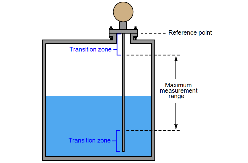
The size of these transition zones depends on both the process substances and the probe type. The instrument manufacturer will provide you with appropriate data for determining transition zone dimensions.

Note : Probe mounting style will also influence the lower transition zone, in the case of flexible probes anchored to the bottom of the process vessel.

Author : Tony R. Kuphaldt – Creative Commons Attribution 4.0 License

Don't Miss Our Updates
Be the first to get exclusive content straight to your email.
We promise not to spam you. You can unsubscribe at any time.
Invalid email address
You've successfully subscribed !

Continue Reading

Servo Tank Gauges Working Principle
DP Transmitter with Two Seals applications
Closed Tank Remote Seal Capillary type DP Transmitter
Difference between Transparent Level Gauge and Reflex Level Gauge
How Buoyant Force instruments Works ?
Guided Wave Radar Questions and Answers
Share This Article
Facebook Whatsapp Whatsapp LinkedIn Copy Link
Share
Leave a Comment

Leave a Reply Cancel reply

Your email address will not be published. Required fields are marked *

Stay Connected

128.3kFollowersLike
69.1kFollowersFollow
210kSubscribersSubscribe
38kFollowersFollow

Categories

Explore More

Types of Level Measurement
Questions on Level Switches
Differential Pressure (DP) Level transmitter Installed Below Tapping Point
What is a Level Switch? Types of Level Switches
Displacer Interface Level Measurement
Radar and Ultrasonic Level Transmitter Practical Problems Troubleshooting
Open Tank Level Measurement using DP Transmitters Animation
Basics of Differential Pressure Level Transmitters

Keep Learning

Instruments Tapping Points

Instruments Tapping Points – Common versus Individual

Nuclear Level Measurement

Nuclear Level Detectors Cascade or Master/Slave concept

DP Transmitters Level Measurement Principle

DP Transmitters Level Measurement Principle Video

Tuning Fork Level Switch principle

Tuning Fork Level Switch Principle

DP-Level-Transmitter-Diaphragm-with-capillary-tube-type

DP Level Transmitter Calibration for Diaphragm Seal with Capillary

Magnetostrictive Tank Gauging Probe

Magnetostrictive Tank Gauging (MTG)

Closed Tank DP Level Transmitter

How to Find LRV and URV of Closed Tank DP Level Transmitter

Capacitance Level Switch Working Principle

Capacitance Level Switch Working Principle

Learn More

Instrumentation and Process Control Project Inputs

Instrumentation and Process Teams Interactions in Design Engineering Companies

Capacitive Level Measurement Principle

Capacitive Level Measurement

Thermocouple Calculations

Thermocouple Calculations

Root Cause Analysis on Hunting of Control Valves

Hunting of Control Valves

Control Valve in PlantPAx Project

Configuration of Control Valve in Studio 5000

Solar Energy

Types of Renewable Energy Sources

memory types in siemens plc

Memory Structure of Siemens PLC

Power MOSFET Safe Operating Area

Power MOSFET Safe Operating Area

Menu

  • About
  • Privacy Policy
  • Copyright

Quick Links

  • Learn PLC
  • Helping Hand
  • Part Time Job

YouTube Subscribe

Follow US
All rights reserved. Reproduction in whole or in part without written permission is prohibited.
Welcome Back!

Sign in to your account

Username or Email Address
Password

Lost your password?