Inter Discipline Check (IDC) is an activity done by Design Engineers in Plant Design Companies. IDC is performed to ensure that the design and engineering output including supplier documentation is meeting the project design requirements by all related internal disciplines.
Contents
Inter Discipline Check (IDC)
Here we shall see which things to check from other discipline’s documents as an Instrumentation Engineer.
Chemical or Process
DOCUMENT – P&ID
Points to Check:
- Instrument legend as per client / ISA standard (mainly for valves and flowmeters)
- Process connection type and size
- Instrument signal type identification – BPCS, SIS
- Addition / Deletion of Specific notes
- Line type – pneumatic, signal line, etc
- Instrument Scope clarification – Vendor vs client, existing vs new instrument
- Isolation valve requirement check
- Instrument tagging Representation
Mechanical
DOCUMENT – VENDOR PACKAGE SPECIFICATION
Points to Check:
- Preferred PLC make
- Preferred Communication Protocol
- HMI/SCADA
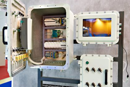
- Control Panel Enclosure MOC
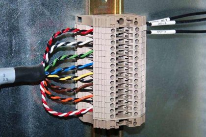
- Interconnecting Cabling, Earthing cables, Wiring, and other Instrument items within the skid
- All interconnecting tubing within the package.
- Necessary Instrumentation & Controls, Instrumentation including interconnecting cable and safety devices
Inter Discipline Check
Skid/Packages
Points to Check:
- Skid-mounted Junction boxes (as per SUPPLIER design) & interconnecting cabling for Instruments within the skid
- Integration of skid/Package wiring in case of delivered in various sections/parts
- Support to DCS Vendor
- Specific Requirement i.e. IBR Certification for Boiler
DOCUMENT – Equipment GA/Datasheet/VDR
Points to Check:
- Process Connection type – size
- Cross-check with P&ID data & ensure data alignment in both the documents
- Instrument Installation check i.e. Nozzle orientation for RADAR transmitter, support arrangement for capacitance type level switch
- The requirement of Remote transmitter (internal point- I&C doc will be updated)
- Check MOC – Optional
- The requirement of Thermowell for Temperature measurement
DOCUMENT – Equipment Layouts
Points to Check:
- JB / RIO / Control panel Installation (input)
- Pipe Rack Requirements (input)
- Cable tray support Requirements (input)
Common
Points to Check:
- Cable tray routing inside the building
- Control panel/JB near equipment/skid,
- conduit routing,
- instrument air tubing
Piping
DOCUMENT – 3D MODEL REVIEW
Points to Check:
- Basic Instruments connection details
- Cable tray routing on Pipe rack
- Instruments as per hook up drawings
Civil and Structure
DOCUMENT – LAYOUTS
Points to Check:
- Wall/Floor cut-out for cable tray routing
Electrical
DOCUMENT – LOAD LIST/LAYOUTS
Points to Check:
- No of motors as per P&ID as Signal consideration for IO list
- Cable tray layouts
- Earth pit layout
- Electrical room layout
- Lighting Layout
Author: Kalpit Patel
Read Next:
- Instrumentation Word Game
- Intrinsic Safety Protection
- Valve Safety Factor
- Polarity of Voltage Drops
- Air Consumption for Valves