Inst ToolsInst ToolsInst Tools
  • Courses
  • Automation
    • PLC
    • Control System
    • Safety System
    • Communication
    • Fire & Gas System
  • Instrumentation
    • Design
    • Pressure
    • Temperature
    • Flow
    • Level
    • Vibration
    • Analyzer
    • Control Valve
    • Switch
    • Calibration
    • Erection & Commissioning
  • Interview
    • Instrumentation
    • Electrical
    • Electronics
    • Practical
  • Q&A
    • Instrumentation
    • Control System
    • Electrical
    • Electronics
    • Analog Electronics
    • Digital Electronics
    • Power Electronics
    • Microprocessor
Search
  • Books
  • Software
  • Projects
  • Process
  • Tools
  • Basics
  • Formula
  • Power Plant
  • Root Cause Analysis
  • Electrical Basics
  • Animation
  • Standards
  • 4-20 mA Course
  • Siemens PLC Course
Reading: As per Process Conditions, Find out the Circuit Components Status ?
Share
Notification Show More
Font ResizerAa
Inst ToolsInst Tools
Font ResizerAa
  • Courses
  • Design
  • PLC
  • Interview
  • Control System
Search
  • Courses
  • Automation
    • PLC
    • Control System
    • Safety System
    • Communication
    • Fire & Gas System
  • Instrumentation
    • Design
    • Pressure
    • Temperature
    • Flow
    • Level
    • Vibration
    • Analyzer
    • Control Valve
    • Switch
    • Calibration
    • Erection & Commissioning
  • Interview
    • Instrumentation
    • Electrical
    • Electronics
    • Practical
  • Q&A
    • Instrumentation
    • Control System
    • Electrical
    • Electronics
    • Analog Electronics
    • Digital Electronics
    • Power Electronics
    • Microprocessor
Follow US
All rights reserved. Reproduction in whole or in part without written permission is prohibited.
Inst Tools > Blog > Instrumentation Design > As per Process Conditions, Find out the Circuit Components Status ?

As per Process Conditions, Find out the Circuit Components Status ?

Last updated: June 6, 2018 9:55 am
Editorial Staff
Instrumentation Design Practical Questions
8 Comments
Share
1 Min Read
SHARE

Determine the statuses of all lamps and relay coils in this circuit, given the following process conditions:
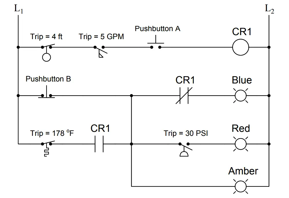
process conditions, Find out the Circuit Components Status

Process Conditions :

  • Flow = 7.9 GPM
  • Pressure = 36 PSI
  • Temperature = 210 Deg F
  • Level = 7.1 ft
  • Pushbutton A = pressed
  • Pushbutton B = unpressed

Answer :

Fully annotated circuit schematic: “X” representing an open contact or de-energized load, and “→” representing a closed contact or energized load.
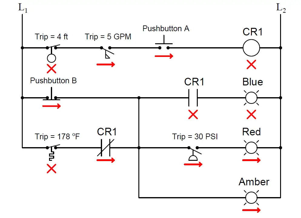
process conditions, Find out the Circuit Components

Recall that a process switch will be in its resting (“normal”) condition when the stimulus value is less than the trip threshold, and will be in its actuated condition when the stimulus exceeds the threshold.

Therefore,

  1. CR1 coil = de-energized
  2. Blue lamp = de-energized
  3. Red lamp = energized
  4. Amber lamp = energized

Share Your Answer / Comments

Credits : by Tony R. Kuphaldt – under CC BY 1.0

Don't Miss Our Updates
Be the first to get exclusive content straight to your email.
We promise not to spam you. You can unsubscribe at any time.
Invalid email address
You've successfully subscribed !

Continue Reading

Air Cylinder Consumption Calculation for Control Valves
Basic Requirements of Control Valves Sizing
Pressure Level Transmitter Problems
Switch or Transmitter
Why we use NAMUR Output Sensor?
Determine the functions of Pressure Switches ?
Share This Article
Facebook Whatsapp Whatsapp LinkedIn Copy Link
Share
8 Comments
  • Sadok says:
    August 27, 2017 at 10:41 am

    Good presentation

    Reply
  • azetou says:
    August 31, 2017 at 8:58 am

    Hi, there is some issues with this exercise:

    First, you changed the program in the answer (Contact of CR1 is normally closed in the second rung and normally open in the third rung) the inverse what it is shown in the question.

    Second, If pushbutton B is unpressed than you are bypassing the Temprature switch and the CR1 contact.

    I think that a more logical program would be as you reported it in the answer with removing the connection between rung 3 and rung 2.

    Reply
    • S Bharadwaj Reddy says:
      August 31, 2017 at 10:30 am

      Hi, For easy understanding, There are some process conditions mentioned below the question, Apply the process conditions to the circuit diagram, so component status in the circuit will change accordingly then answer.

      Reply
  • azetou says:
    August 31, 2017 at 9:04 am

    it is a bit confusing, better to put programs that works in the real world.

    Reply
  • azetou says:
    August 31, 2017 at 9:30 am

    Just wondering , these answers are from Ton Kuphaldt or from you Mr Bharadwaj ???

    Reply
    • S Bharadwaj Reddy says:
      August 31, 2017 at 10:13 am

      by Mr. Tony R Kuphaldt

      Reply
      • azetou says:
        August 31, 2017 at 10:54 am

        Thank you.

        Reply
  • Akhil says:
    June 10, 2019 at 2:11 pm

    HI sir,

    First of all thank you sir for providing such a platform to study instrumentation. You are doing a great work.

    I have one doubt regarding the answer of these question.The ladder logic shown in the question has NC relay in the second rung and a NO relay in the third rung and they are in denergized state.

    After applying the process parameters to this ladder logic,it is observed that the CR1 coil is not energised,so then correspondingly the 2 relays are also not energised because they depend upon the coil CR1

    But in the answer it is shown that the relay state is changed,I think the ladder logic diagram shown in the question and answer are different.

    I think the answer will be,

    1.CR1 coil denergised
    2.Blue lamb energised
    3.Red lamb energised
    4.Amber lamb energised

    Awaiting your replay,
    Thank you sir.

    Reply

Leave a Reply Cancel reply

Your email address will not be published. Required fields are marked *

Stay Connected

128.3kFollowersLike
69.1kFollowersFollow
208kSubscribersSubscribe
38kFollowersFollow

Categories

Explore More

What is the Purpose of Bourdon Tube Gauge Spiral Spring?
Measure the Temperature of the RTD
Solenoid-controlled Valve Problem
Determine the Instrument Calibration Error
Instrumentation and Control (I&C) Design
Why We use Shielded Cable and Twisted Pair Cables ?
Upgrading the Electrical System in an Automobile
Pneumatic Level Transmitter Calibration Table

Keep Learning

LRV and URV of PT for Extreme Limits of Empty and Full

LRV and URV of PT for Extreme Limits of Empty and Full

What is WHCP?

Selecting Directional Valves

How to Select a Directional Valves

Monsoon Protection for Field Instruments and Junction Boxes

Monsoon Protection for Field Instruments and Junction Boxes

Air Consumption Calculation for Control Valves

Air Consumption Calculation for ON/OFF Valves

How Much Pressure indicated by Micromanometer

How Much Pressure Indicated by Micromanometer?

Pressure Gauge Maintenance and Troubleshooting

Pressure Gauge Maintenance and Troubleshooting

Calculation of Hydrostatic Pressure

Calculation of Hydrostatic Pressure

Learn More

Comparison of Accuracy and Precision

Difference between Accuracy and Precision

Electrical Machines Questions and Answers

DC Motors Characteristics Quiz

Calibration of Temperature Sensor with Indicator

Calibration of Temperature Sensor with Indicator

wedge Flow meter

What is a Segmental Wedge Flow Meter?

How to Implement Ratio Control in this System

How to Implement Ratio Control in this System?

DP transmitter Elevated 10 Feet above the Vessel

DP transmitter Elevated 10 Feet above the Vessel

Top PLC Manufacturers

Top PLC Manufacturers

PID Setup

PID in Studio 5000

Follow US
All rights reserved. Reproduction in whole or in part without written permission is prohibited.
Welcome Back!

Sign in to your account

Username or Email Address
Password

Lost your password?