Inst ToolsInst ToolsInst Tools
  • Courses
  • Automation
    • PLC
    • Control System
    • Safety System
    • Communication
    • Fire & Gas System
  • Instrumentation
    • Design
    • Pressure
    • Temperature
    • Flow
    • Level
    • Vibration
    • Analyzer
    • Control Valve
    • Switch
    • Calibration
    • Erection & Commissioning
  • Interview
    • Instrumentation
    • Electrical
    • Electronics
    • Practical
  • Q&A
    • Instrumentation
    • Control System
    • Electrical
    • Electronics
    • Analog Electronics
    • Digital Electronics
    • Power Electronics
    • Microprocessor
  • Request
Search
  • Books
  • Software
  • Projects
  • Process
  • Tools
  • Basics
  • Formula
  • Power Plant
  • Root Cause Analysis
  • Electrical Basics
  • Animation
  • Standards
  • 4-20 mA Course
  • Siemens PLC Course
Reading: Valve Safety Factor
Share
Font ResizerAa
Inst ToolsInst Tools
Font ResizerAa
  • Courses
  • Design
  • PLC
  • Interview
  • Control System
Search
  • Courses
  • Automation
    • PLC
    • Control System
    • Safety System
    • Communication
    • Fire & Gas System
  • Instrumentation
    • Design
    • Pressure
    • Temperature
    • Flow
    • Level
    • Vibration
    • Analyzer
    • Control Valve
    • Switch
    • Calibration
    • Erection & Commissioning
  • Interview
    • Instrumentation
    • Electrical
    • Electronics
    • Practical
  • Q&A
    • Instrumentation
    • Control System
    • Electrical
    • Electronics
    • Analog Electronics
    • Digital Electronics
    • Power Electronics
    • Microprocessor
  • Request
Follow US
All rights reserved. Reproduction in whole or in part without written permission is prohibited.
Inst Tools > Blog > Control Valves > Valve Safety Factor

Valve Safety Factor

Last updated: May 28, 2020 10:12 am
Editorial Staff
Control Valves
2 Comments
Share
2 Min Read
SHARE

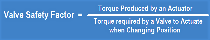
During designing an actuated valve, instrument engineer shall concern to valve safety factor which is a ratio between “torque produced by an actuator” to “torque required by a valve to actuate when changing position” (close to open or vice versa).

Valve Safety Factor

Safety Factor Formula for Control Valve

Valve and actuator commonly obtained from different manufacturer, therefore it is a responsibility of instrument engineer to ensure that combination of the selected valve and actuator will operate properly and meet the safety factor specified by project.

To obtain the information simply doing the following step.

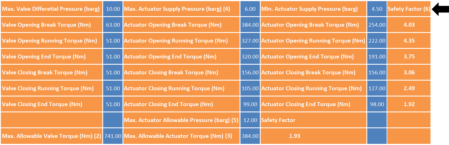
After deciding valve size, valve rating, valve material, etc., go to valve catalog and select one valve that meet the specification. Then, obtain valve torque data. Valve torque is affected by maximum differential pressure across valve (Max dP). This value is determined by process department and shall be informed to vendor. Max dP usually occurs when valve is fully close so that one side at maximum pressure while the opposite site is at no process fluid condition.

Afterwards select an actuator that can produce torque higher than the required valve torque. Note that torque produced by an actuator is affected by power source, e.g. instrument air pressure in pneumatic actuator.

Usually vendor will provided safety factor table along with quotation, following with engineering review.

Below is one example of safety factor table:

Valve Safety Factor

What is the recommended safety factor value?

Many projects require 1.5 or 2.

Note that safety factor which is too high could lead to miss-operation of an actuated valve.

Read Next:

  • Hydraulic Actuator Principle
  • Control Valve Lift DP
  • What is BDV and PSV?
  • Instrument Air Design
  • Solenoid Actuated Valve

Source: instrument-control blog

Don't Miss Our Updates
Be the first to get exclusive content straight to your email.
We promise not to spam you. You can unsubscribe at any time.
Invalid email address
You've successfully subscribed !

Continue Reading

Metal Seated Valves and Soft Seated Valves : Differences
Working Principle of Pneumatic Actuators
Control Valve Performance with Varying Pressure
Pneumatic Directional Control Valves
How do you do control valve sizing in Layman’s terms?
Types of Control Valves
Share This Article
Facebook Whatsapp Whatsapp LinkedIn Copy Link
Share
2 Comments
  • Deepak kumar says:
    September 24, 2021 at 2:20 pm

    During Actuator Sizing Valve Safety Factor fail what to do.
    change the actuator spring range or change the valve stem material.

    Reply
    • Deepak kumar says:
      October 15, 2021 at 4:04 pm

      Any Reply Plz?

      Reply

Leave a Reply Cancel reply

Your email address will not be published. Required fields are marked *

Stay Connected

128.3kFollowersLike
69.1kFollowersFollow
210kSubscribersSubscribe
38kFollowersFollow

Categories

Explore More

Control Valve Packing
Difference between Rotary Shaft Valves and Sliding Stem Control Valves
How to Choose a Control Valve?
What is Mixing or Diverting Valve ?
Control Valves Pre-Commissioning Checklist
Basics of Globe Valves
Control Valve Questions and Answers
Facts About Control Valves

Keep Learning

Control Valve in Last Position

Control Valve Fail Safe Action

Selecting the Proper Failure Mode

How to Select Control Valve Failure Mode

Installation of a Control Valve

How to Install a Control Valve?

Gate Valve

How Gate Valves Work ?

Valve Actuator Passing

Lessons Learned from Actuator Passing Incidents

Gate Valve Parts

What is Gate Valve ?

Pneumatic Actuators

Self-Actuated Valves, Pneumatic & Hydraulic Actuators

Steam conditioning valves

Concept of Steam Conditioning Valves

Learn More

Hydrostatic Level Measurement

Hydrostatic Level Measurement

Top 100 Robotic Projects for Engineering Students

Top 100 Robotic Projects for Engineering Students

Pressure Gauge Calibration according to Standard DKD-R-6-1

Pressure Gauge Calibration according to Standard DKD-R-6-1

valve trim characteristics

Control Valve Trim Characteristics

Ladder Diagram circuit

PLC Practice Questions

strain gauge with Diaphragm

Strain Gauge Working Principle

How to Use Loop Calibrator

Troubleshooting with Loop Calibrator

Porpoising PID Controller

Recognizing a Porpoising PID Controller

Menu

  • About
  • Privacy Policy
  • Copyright

Quick Links

  • Learn PLC
  • Helping Hand
  • Part Time Job

YouTube Subscribe

Follow US
All rights reserved. Reproduction in whole or in part without written permission is prohibited.
Welcome Back!

Sign in to your account

Username or Email Address
Password

Lost your password?