Inst ToolsInst ToolsInst Tools
  • Courses
  • Automation
    • PLC
    • Control System
    • Safety System
    • Communication
    • Fire & Gas System
  • Instrumentation
    • Design
    • Pressure
    • Temperature
    • Flow
    • Level
    • Vibration
    • Analyzer
    • Control Valve
    • Switch
    • Calibration
    • Erection & Commissioning
  • Interview
    • Instrumentation
    • Electrical
    • Electronics
    • Practical
  • Q&A
    • Instrumentation
    • Control System
    • Electrical
    • Electronics
    • Analog Electronics
    • Digital Electronics
    • Power Electronics
    • Microprocessor
  • Request
Search
  • Books
  • Software
  • Projects
  • Process
  • Tools
  • Basics
  • Formula
  • Power Plant
  • Root Cause Analysis
  • Electrical Basics
  • Animation
  • Standards
  • 4-20 mA Course
  • Siemens PLC Course
Reading: Calculate Flow Coefficient Kv of Solenoid Valve
Share
Font ResizerAa
Inst ToolsInst Tools
Font ResizerAa
  • Courses
  • Design
  • PLC
  • Interview
  • Control System
Search
  • Courses
  • Automation
    • PLC
    • Control System
    • Safety System
    • Communication
    • Fire & Gas System
  • Instrumentation
    • Design
    • Pressure
    • Temperature
    • Flow
    • Level
    • Vibration
    • Analyzer
    • Control Valve
    • Switch
    • Calibration
    • Erection & Commissioning
  • Interview
    • Instrumentation
    • Electrical
    • Electronics
    • Practical
  • Q&A
    • Instrumentation
    • Control System
    • Electrical
    • Electronics
    • Analog Electronics
    • Digital Electronics
    • Power Electronics
    • Microprocessor
  • Request
Follow US
All rights reserved. Reproduction in whole or in part without written permission is prohibited.
Inst Tools > Blog > Control Valves > Calculate Flow Coefficient Kv of Solenoid Valve

Calculate Flow Coefficient Kv of Solenoid Valve

Last updated: April 19, 2019 7:06 pm
Editorial Staff
Control Valves Formulas Instrumentation Design Solenoid Valve
1 Comment
Share
3 Min Read
SHARE

Flow Coefficient Kv

Definition Kv-value: Amount of flow (m3/hour) of water of 20°C in a valve with a pressure loss of 1 bar.

The amount of flow of a fluid through a (solenoid) valve can easily be calculated with flow coefficient Kv. Please note that for gases (e.g. air) a different formula is used (see correction factor gases below).

Contents
Flow Coefficient KvCv & Kv Relation :Correction Factor For GasesExample

The Kv-value expresses the flow rate of water in m3/hour in a valve with a pressure loss of 1 bar and a temperature of 20°C. Pay attention that the Kv-value is expressed in m3/hour, while the kv-value (lowercase!) is expressed in l/min.

To calculate the flow rate the following formula is used:

Flow Coefficient Kv

where:

  • Q = flow rate of liquid (m3/hour)
  • Kv = flow coefficient (m3/hour)
  • SG = Specific Gravity (=1 for water)
  • dp = pressure differential over the valve (bar)

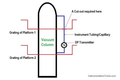
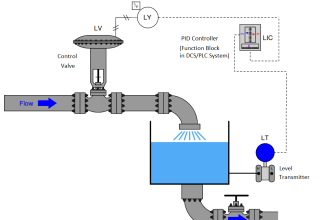
The Kv-value of a valve is determined by a standardized test according to VDI/VDE 2173. For this purpose a test set-up is used, such as shown in the following schematic drawing:

Kv-value of a valve is determined

Cv & Kv Relation :

Sometimes, the Cv value is given instead of the Kv value. The Cv value can be converted to the Kv-value with a conversion factor:

  • Cv = 1.16 Kv
  • Kv = 0.853 Cv

The diagram below is a nice tool to simplify the conversion between the different coefficients. The conversion factor between two coefficients is indicated with arrows.

Cv and Kv Relation of Valve

Kv (with a capital K) expresses the flow rate in m3/hour, kv (lowercase) in l/min.

Valves In Parallel:

If several valves are connected in parallel, the Kv value can be determined simply by adding up all Kv values.

Correction Factor For Gases

When using gases, a different formula for the flow rate should be used. Also, a distinction between subsonic and supersonic flows is made. “Qn” indicates that the formula is valid for standard conditions (20°C).

The flow rate is expressed in Nm3/h (Normal cubic metre per hour).

Correction Factor For Gases

Where:

  • dP = pressure loss (bar)
  • Kv = flow coefficient (m3/hour)
  • p1 and p2 are respectively the absolute inlet and outlet pressure (bar)
  • ? = specific gravity at standard conditions (20°C) in kg/m3
  • T = absolute temperature in Kelvin (0K = -273.15°C)

Example

Consider a circuit with a solenoid valve with an inlet pressure (water) of 5 bars. The required flow rate is at least 5 litres per minute. The maximum allowed pressure loss is 1 bar, therefore the outlet pressure is minimally 4 bars. What is the minimum required Kv-value?

minimum required Kv-value

The Kv-value must be at least 0.3.

Also Read: Control Valve Cv Calculation

Don't Miss Our Updates
Be the first to get exclusive content straight to your email.
We promise not to spam you. You can unsubscribe at any time.
Invalid email address
You've successfully subscribed !

Continue Reading

What is a Disc Valve ?
How to Select Control Valve Failure Mode
Instrumentation Deliverables Generated from 3D Modeling
Over Pressure cases for Pressure Relief Valve Sizing
Rotary Stem Valves
Troubleshooting Common Control Valve Problems
Share This Article
Facebook Whatsapp Whatsapp LinkedIn Copy Link
Share
1 Comment
  • naveen says:
    December 24, 2021 at 1:31 pm

    How we need to calculate Size and percentage of opening of valve? is there any cv table for solinoid valve

    Reply

Leave a Reply Cancel reply

Your email address will not be published. Required fields are marked *

Stay Connected

128.3kFollowersLike
69.1kFollowersFollow
210kSubscribersSubscribe
38kFollowersFollow

Categories

Explore More

Air Pressure Regulator Questions
Formula to Calculate 4-20ma from Percentage
Spring and Diaphragm Pneumatic Actuators
How to Design a System Architecture in Industrial Automation?
History of 3-15 psi, 10-50 mA, and 4-20 mA signals
Voting Concept in Package Safety System
Automated Block Valve (ABV)
Instrument Protection Methods: Seals

Keep Learning

Solenoid Valve Terminology

Solenoid Valves Terminology

Field Instruments Scaling and Unit Conversions

Field Instruments Scaling and Unit Conversions

Failsafe interlock Design

Failsafe Wiring Practices

Control Valve Recommended Practices

Control Valve Recommended Practices for Harsh Process Conditions

Valve Technician Interview Questions

Valve Technician Interview Questions

Magnetic Flow Meter Corrosion Effects

Magnetic Flow Meter Corrosion Effects

Solenoid Actuated Valves

Solenoid Actuated Valves

Cables Sheath Material

Instrument Cables Sheath Material

Learn More

Free Download Industrial Control System Book

Free Download Industrial Control System Book

Linear Heat Detector Working Principle

What are Linear Heat Detectors?

Changing Process Medium Density has no influence on Level Indication (Full Absorption)

Nuclear Interface Level Measurement Principle, Limitations, Installation and Calibration

Load Cell Assembly

Urea Bagging Plant – Process Flow

Electric Motor Actuators

What is Motor Actuator ?

Oil in Water Analyzer Principle

Oil in Water Analyzer Working Principle

Applications of Robots

Applications of Robots in Various Fields

Troubleshooting Magnetic Flow Meters Common Problems

Troubleshooting Magnetic Flow Meters Common Problems

Menu

  • About
  • Privacy Policy
  • Copyright

Quick Links

  • Learn PLC
  • Helping Hand
  • Part Time Job

YouTube Subscribe

Follow US
All rights reserved. Reproduction in whole or in part without written permission is prohibited.
Welcome Back!

Sign in to your account

Username or Email Address
Password

Lost your password?