In this article, we are going to discuss when to use common tapping points and individual tapping points for the measuring instruments.
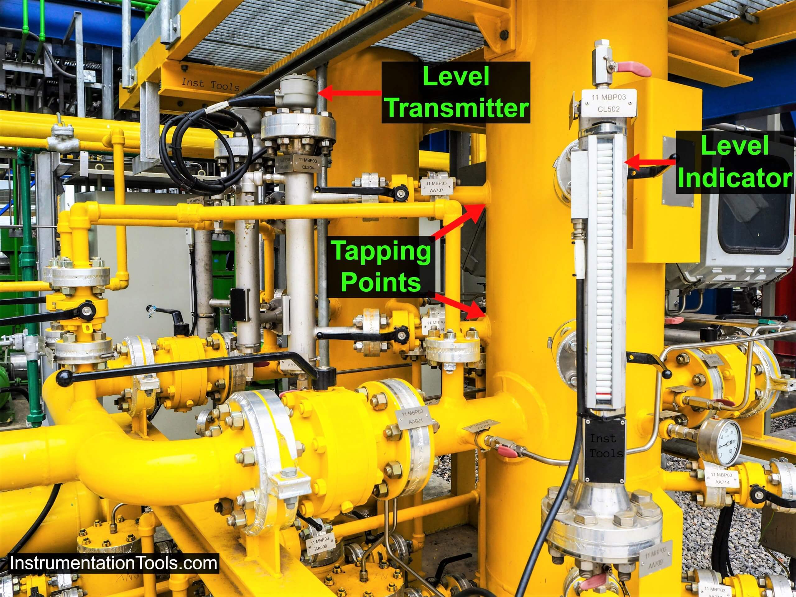
Instruments Tapping Points
IEC 61511 standard suggests an important issue to be considered is whether there are any common cause failures between redundant parts within each layer.
It is very much important to identify and take account of common cause failures.
Single failure due to the common cause may lead to the failure of multiple devices at the same time.
Here we discuss how to choose between common tapping points and individual tapping points for instruments like level transmitters, flow transmitters, orifice plates, etc.
Whenever multiple sensors are used for the same process measurement, the instrument designer must consider the common cause factors.
A common cause failure is defined as “the failure of one or more devices due to common stress event”.
Examples of common cause failures leading to systematic failures usually include human errors in design, operation, and maintenance.
While some systematic failures may be relatively easy to identify (e.g., a design error), the exact number or percentage of such failures is usually more difficult to quantify.
When this occurs then the redundancy is less effective.
Good Engineering Practices
To reduce the common cause of failure following are some of the good engineering practices examples
1) When redundant sensors are physically and electrically separated, there is less likelihood of sensors being subjected to the common cause of failure.
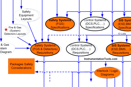
2) SIS instruments shall have independent tapping directly from the equipment or pipe.
3) Instruments used for Safety Instrumented System (SIS) shall be provided separately from those for control and measurement.
4) ONLY elements such as orifice plates and bluff bodies of vortex meters may be shared with control measurements and SIS.
5) For the orifice flow element, a separate set of tapping for each flow transmitter for shutdown/interlock shall be considered.
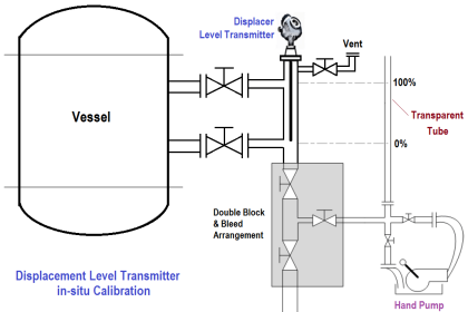
6) Level Transmitters for interlock shall be from independent tapping (for 2oo3 all three LTs shall be from independent tapping directly on equipment).
7) If Control and SIS sensors share a common level bridle, any common valve that can isolate both the control and SIS transmitter shall have administrative controls in place, audited car seal or valve locks, to assure the valves are in the open position.
The management of the administrative controls shall be part of the site SIS Management Plan.
In the above case, if the common shared tapping is used for multiple same measurements, one operator mistake (e.g. closing the common isolation valve) will lead to either a spurious trip or may put the entire system into a dangerous situation.
Few different cases: Rosemount 5900S Level transmitter can be delivered with two independent electronic units in one housing. This unique 2-in-1 solution can serve as a safety-certified level device in two independent protection layers (i.e. DCS and SIS). This requires only one tank opening, which reduces installation costs.
One has to justify the design for cost-saving vs putting the system into danger/ having more spurious trips in the plant due to common cause.
A simple phrase sums up fairly well, “Don’t put all your eggs in one basket.” No matter how reliable the basket may be, there will always be some unknown circumstances where it will drop. Everything fails, it’s just a matter of when.
Interest to add any other points? Any questions? Share with us through the below comments section.
Author: Jatin Katrodiya
If you liked this article, then please subscribe to our YouTube Channel for Instrumentation, PLC, SCADA, and Industrial Automation video tutorials.
You can also follow us on Facebook and Twitter to receive daily updates.