Types of failures in control valves explained in detail and mentioned the possible practical solutions.
If the control valve malfunctions, the performance of the control loop is probably going to deteriorate, irrespective of how good the controller is. The control loop performance is improved by troubleshooting the following few control valve failures.
Control Valves Failures
Common failures related to control valves are
- Dead band
- Static Friction
- Valve sizing
- Nonlinearity
Dead band:
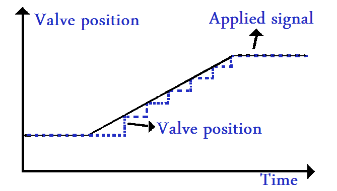
A valve with dead-band acts like there’s is some backlash between the controller output and also the actual valve position. At anytime the controller output changes, it’s direction, the dead band has to be traversed before the valve physically starts moving.
Although the dead band may be caused by the clearances in a mechanism caused by gaps between parts with mechanical looseness or play in mechanical linkages.
it can also be caused by
- excessive friction in the valve,
- an undersized actuator,
- or a defective positioner.
Deadband is also known as mechanical backlash and is often larger in rotary valves because of rotary actuator and shaft coupling design or the need to translate from vertical to rotary motion.
In rotary valves, shaft windup can occur, where the actuator shaft twists but the ball or disc doesn’t move because of high friction of the sealing surfaces. Eventually, in the end, the ball or disc breaks free and jumps to a new position. If the positioner, irrespective of how smart it thinks it is, measures actuator shaft position rather than ball or disc travel, it’s going to report everything is comparatively OK.
Please note that and don’t be confused with the term Hysteresis, as a dead band and hysteresis both are different.
Static Friction:
Another very common problem found in control loops is static friction. Stiction is short for Static Friction and means that the valve internals is sticky. If a valve with stiction stops moving, it tends to stick in that position only. Then extra force is required to overcome the stiction.
Even when the controller continues to change its output while the valve continues to stick in position. Additional pressure mounts in the actuator. If sufficient pressure builds up to overcome the static friction, the valve breaks free.
The valve movement quickly sucks up the excess in pressure, and many times the valve overshoots its target position. After this, the valve variation stops, and the valve get sticks in the new position. Regularly, this overshoot in valve position causes the process to overshoot its set point.
Then the valve sticks at the new position, the controller output reverses in direction, and also the whole process repeats in the opposite direction.
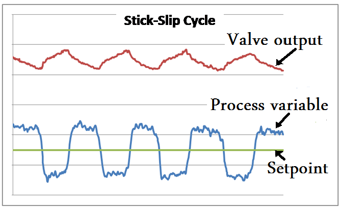
This causes an oscillation, called a stick-slip cycle. If loop oscillations are caused by static friction, the controller output’s cycle often looks like a saw-tooth wave, while the process variable may look like a square wave or an irregular sine wave.
In the case of cage guided valves, the area between the plug and cage is noteworthy, but there should be a soft seal between them. The soft seal is used for preventing leakage, but it also mitigates friction.
How to Avoid Valve Stem Packing Friction?
Stick-slip normally begins from friction in stem packing or from sealing surfaces on the trim.
Excessive tightening of the packing, high-temperature packing (e.g. graphite), older types of environmental packing, tight shutoff ball and disc seals, and low gain or spool positioner designs create more stick-slip.
Stem packing friction can be reduced by using
1. Material of packing
2.Number of packings
3.Load on packing
Graphite and PTFE material is used for low compression packings.
- Graphite packing above 200 deg C
- PTFE packing below 200 deg C.
An appropriate number of packings to balance friction and leakage.
Over tightening of Packing nut may cause excessive friction.
Valve Sizing:
Over-sizing of the valve affects the process variability in two ways.
- The over-sized valve is less flexible in adjusting the controller.
An oversized control valve is often operating more regularly at lower value openings where seal friction is often greater in rotary valves.
Even though actual inherent valve characteristics, a severely oversized valve tends to act more like a quick opening valve.
- An oversized valve tends to act more like a quick opening valve even though having actual inherent valve characteristics.
Nonlinearity:
An inappropriately selected valve with inherent flow characteristic will result in a non-linear installed flow characteristic. The result is a system that will be very difficult or even become impossible to tune for fast, stable response throughout the required flow range.
On the other hand, a valve with properly selected inherent flow characteristics will produce a linear, or nearly linear, installed flow characteristic, making it very easy to tune the system for a very fast, stable response throughout the entire required flow range.
Source: enggjournals
Read Next:
- Emergency Shutdown Valve
- Control Valve Travel Stop
- Compare BDV and PSV
- Types of Valve Actuators
- Control Valve Cv versus Kv


It’s been a wonderful Techinical lecture for me as a Mitsubishi l200 owner
Stay blessed plz