The IEC also defines how manufacturers should mark the values of resistors and capacitors in the standard called IEC 60062. The colours used on fixed leaded resistors are shown below:
Colour code marking of leaded resistors
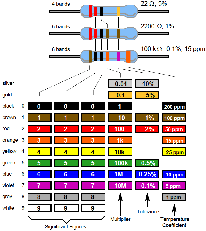
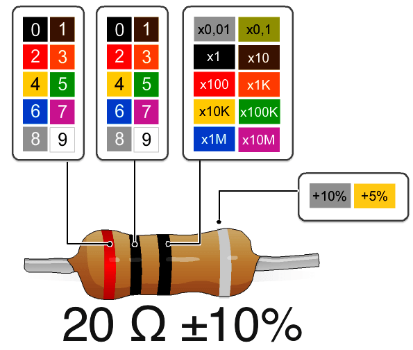
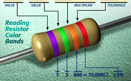
The resistance colour code consists of three or four colour bands and is followed by a band representing the tolerance. The temperature coefficient band, if provided, is to the right of the tolerance band and is usually a wide band positioned on the end cap.
The resistance colour code includes the first two or three significant figures of the resistance value (in ohms), followed by a multiplier. This is a factor by which the significant-figure value must be multiplied to find the actual resistance value. (i.e. the number of zeros to be added after the significant figures).
Whether two or three significant figures are represented depends on the tolerance: ±5% and wider require two band; ±2% and tighter requires three bands. The significant figures refer to the first two or three digits of the resistance value of the standard series of values in a decade, in accordance with IEC 60063 as indicated in the relevant data sheets and shown in Below Table.
The colours used and their basic numerical meanings are recognized internationally for any colour coding used in electronics, not just resistors, but some capacitors, diodes, cabling and other items.
The colours are easy to remember: Black is the absence of any colour, and therefore represents the absence of any quantity, 0. White (light) is made up of all colours, and so represents the largest number, 9. In between, we have the colours of the rainbow: red, orange, yellow, green, blue and violet. These take up the numbers from 2 to 7. A colour in between black and red would be brown, which has the number 1. A colour intermediate to violet and white is grey, which represents the number 8.
When resistors are labelled in diagrams, such as schematics, IEC 60062 calls for the significant figures to be printed as such, but the decimal point is replaced with the SI prefix of the multiplier. Examples of such labelling are shown below:
IEC labelling for Resistors
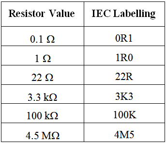
Note how the decimal point is expressed, that the ohm symbol is shown as an R, and that 1000 is shown as a capital K. The use of a letter instead of a decimal point solves a printing problem – the decimal point in a number may not always be printed clearly, and the alternative display method is intended to help misinterpretation of component values in circuit diagrams and parts lists.
In circuit diagrams and constructional charts, a resistor’s numerical identity, or designator, is usually prefixed by ‘R’. For example, R15 simply means resistor number 15.
A portion of a schematic diagram showing designators and IEC labelling is shown below:
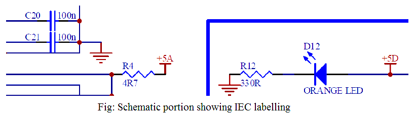
Note that resistor R4 has the value 4.7 Ω and resistor R12 has the value 330 Ω.