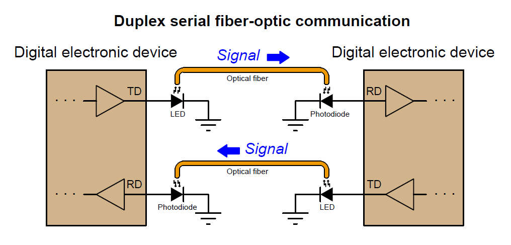
An optical fiber is a “pipe” through which light flows. This is, of course, merely an analogy for how an optical fiber works, but it conveys the basic idea. The interface between a piece of electronic equipment and an optical fiber consists of an optical source (typically an LED or a semiconductor laser) to generate light signals from electrical signals, and an optical detector (typically a photodiode or phototransistor) to generate electrical signals from received light signals.
The predominant use of optical fiber in modern industry is as a data communication medium between digital electronic devices, replacing copper-wire signal and network cabling. An illustration showing two digital electronic devices communicating over a pair of optical fibers appears here, each fiber “conducting” pulses of light (representing serial digital data) from an LED source to a photodiode detector:
The following photograph shows a serial converter (the black rectangular plastic box with a blue label) used to convert optical data pulses entering and exiting through orange-jacketed optical cables (on the left) into EIA/TIA-232 compliant electrical signals through a DB-9 connector (on the right) and vice-versa, allowing the electronic serial data device on the right-hand side of the photograph to communicate via fiber optic cabling:
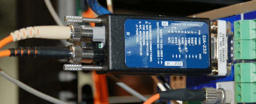
Note how the two optical fiber ports on the converter body are labeled “R” and “T” for Receive and Transmit, respectively. Serial devices with built-in electronic/optical converters will similarly label their optical ports.
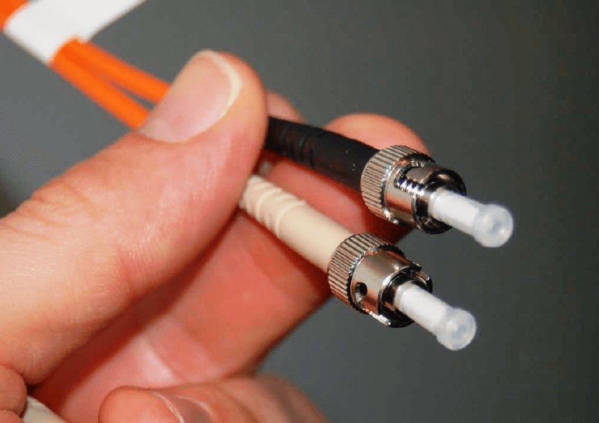
For this device, connection to each of the optical fibers is made using an “ST” style connector, with a quarter-turn locking ring holding each one in place (much like the quarter-turn barrel body of a “BNC” style electrical connector). The next photograph shows a pair of optical fibers terminated with ST-style connectors. White plastic caps cover the connector tips, keeping the glass fiber ends protected from dust and abrasion:
As a data pathway, optical fiber enjoys certain advantages over electrical cable, including:
- Much greater bandwidth (data-carrying capacity), estimated to be in the terahertz range
- Much less equivalent signal power loss per unit cable length (less than 1 dB per kilometer compared with 25 dB per kilometer for coaxial cable)
- Complete immunity to external “noise” sources
- No radiation of energy or data from the cable, thus will not create interference nor be liable to eavesdropping
- No electrical conductivity, allowing safe routing of cables near high voltage conductors
- Total galvanic isolation (i.e. no electrically conductive connection) between data devices, allowing operation at different electrical potentials
- Safe for use in areas with explosive vapors, dust, and/or fibers
These advantages deserve some elaboration. The superior bandwidth of fiber-optic cable is so dramatic that the present-day limitation on data transfer rates for most fiber-optic installations is the electronic devices at each end, and not the optical fiber itself! This, combined with the low inherent power loss of optical fiber, makes it an ideal medium for long-range data communication such as telephone and internet. Thousands of miles of optical fiber cable have been buried in underground trenches, laid down on sea floors, strung as overhead lines, and used as “patch” cables in room-scale applications since the advent of affordable optical cabling in the 1980’s. The “tech boom” of the 1990’s saw an impressive amount of trans-continental and inter-continental optical fiber installation, paving the way for the global expansion of internet services into the 21st century.
The limitations of electronics at each end of these long fibers means we have not yet begun to tap their full data-carrying capacity, either. Conveying data in photonic – as opposed to electronic – form means there is absolutely no such thing as capacitive or inductive coupling with external systems as there is with conductive wire cable, which not only means optical fiber communication is immune to external interference but also that the optical signals cannot create interference for any other system. Since optical fibers are customarily manufactured from glass which is electrically non-conductive, it is possible to route optical fibers alongside high-voltage power lines, and also connecting together devices at vastly different electrical potentials from each other, with no risk of bridging those differing potentials. Finally, the low power levels associated with optical fiber signals also makes this technology completely safe in areas where explosive compounds in the atmosphere might otherwise be ignited by faults in electrical communications cable.
Optical fibers also suffer from some unique limitations when compared against electrical cable, including:
- Need to avoid tight bend radii for optical cables
- Connections need to be extremely clean
- Specialized tools and skills necessary for installation and maintenance
- Expensive testing equipment
While electrical “transmission line” signal cables must also avoid sharp bends and other discontinuities caused by cramped installations, this need is especially pronounced for optical fiber (for reasons which will be explained later in this section). Since fiber-to-fiber connections consist of glass pressed against glass, the presence of even microscopic contaminants such as dust particles may damage fiber optic connectors if they aren’t cleaned prior to insertion. Cutting, preparing, and terminating optical fiber cables requires its own set of specialized tools and skills, and is not without unique hazards. Lastly, the test equipment necessary to check the integrity of an optical pathway is similarly specialized and typically quite expensive.