Inst ToolsInst ToolsInst Tools
  • Courses
  • Automation
    • PLC
    • Control System
    • Safety System
    • Communication
    • Fire & Gas System
  • Instrumentation
    • Design
    • Pressure
    • Temperature
    • Flow
    • Level
    • Vibration
    • Analyzer
    • Control Valve
    • Switch
    • Calibration
    • Erection & Commissioning
  • Interview
    • Instrumentation
    • Electrical
    • Electronics
    • Practical
  • Q&A
    • Instrumentation
    • Control System
    • Electrical
    • Electronics
    • Analog Electronics
    • Digital Electronics
    • Power Electronics
    • Microprocessor
  • Request
Search
  • Books
  • Software
  • Projects
  • Process
  • Tools
  • Basics
  • Formula
  • Power Plant
  • Root Cause Analysis
  • Electrical Basics
  • Animation
  • Standards
  • 4-20 mA Course
  • Siemens PLC Course
Reading: What is Infrared Flue Gas Analyzer? – Working Principle
Share
Notification Show More
Font ResizerAa
Inst ToolsInst Tools
Font ResizerAa
  • Courses
  • Design
  • PLC
  • Interview
  • Control System
Search
  • Courses
  • Automation
    • PLC
    • Control System
    • Safety System
    • Communication
    • Fire & Gas System
  • Instrumentation
    • Design
    • Pressure
    • Temperature
    • Flow
    • Level
    • Vibration
    • Analyzer
    • Control Valve
    • Switch
    • Calibration
    • Erection & Commissioning
  • Interview
    • Instrumentation
    • Electrical
    • Electronics
    • Practical
  • Q&A
    • Instrumentation
    • Control System
    • Electrical
    • Electronics
    • Analog Electronics
    • Digital Electronics
    • Power Electronics
    • Microprocessor
  • Request
Follow US
All rights reserved. Reproduction in whole or in part without written permission is prohibited.
Inst Tools > Blog > Analyzers > What is Infrared Flue Gas Analyzer? – Working Principle

What is Infrared Flue Gas Analyzer? – Working Principle

In this article, we will discuss the Infrared Flue Gas analyzer used in industries and its working principle.

Last updated: September 28, 2022 3:31 pm
Shiv Kumar
Analyzers
No Comments
Share
5 Min Read
SHARE

In this article, we will discuss the Infrared Flue Gas analyzer and its working principle.

Contents
Infrared Flue Gas AnalyserAnalyzer Working Principle

Here the portion of the infrared spectrum gets absorbed when the infrared beam passes through certain gases like carbon monoxide and carbon dioxide.

The amount of gas that is passed can be determined by the amount of a particular frequency of light absorbed by the gas when the light is passed through the gas.

The gases like carbon monoxide, carbon dioxide, and many other gases have infrared absorption characteristics. But elemental diatomic gases such as oxygen, hydrogen, nitrogen, etc. do not exhibit such characteristics.

The concentration of any of the components that indicates the infrared absorption characteristics in a mixture is determined by its unique absorption pattern.

Infrared Flue Gas Analyser

Infrared Flue Gas Analyzer

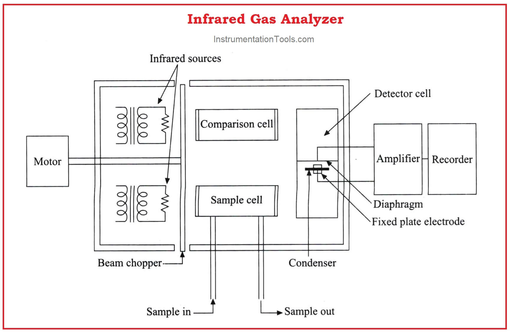
The above figure shows an infrared analyzer using infrared techniques. Two similar infrared sources may be Nichrome filaments used as infrared radiation sources.

The light beams from the sources are made to travel through the sample cell and comparison cell respectively.

A mechanism called beam chopper in the analyzer in between the source and the cells is operated so that it alternatively interrupts the light radiation to the sample cell and comparison cell.

The emergent radiation from both the sample cell and the comparison cell enters the opposite ends of a detector cell.

This detector cell is divided into two compartments by a metallic diaphragm and is filled with the gas to be measured at the same pressure.

Further processing is made with the condenser connected with the amplifier and is formed by combining a metallic diaphragm and the fixed electrode.

The different molecules present in the air absorb different light frequencies. The absorbed frequency which is measured will clearly say the relation to the amount of particular gas in the air.

For every optical analyzer and for every absorption type, the absorption spectrum of infrared radiation is unique for various gases.

The beer Lambert’s law gives the fundamental equation relating photon absorption to substance concentration.

Analyzer Working Principle

The comparison cell is filled with any of the diatomic gases like O2, N2, or Hydrogen. That does not absorb infrared energy.

The sample cell is also filled with the same diatomic gas as in the comparison cell for adjusting the zero of the analyzer. Then the sample gas is made to pass through the sample cell.

The absorption rate of infrared energy depends upon the components present in the sample.

In this case, Let us assume measuring CO components.

The detector cell is filled with Carbon Monoxide gas on both sides. When the unit is under operation the energy received from the sample side in the detector will be less by an amount equivalent to the CO2 component present in the sample compared to the energy received from the comparison cell.

The difference in energy levels received and finally, absorbed by CO2 present on both sides of the detector cell will cause temperature and hence pressure difference.

As the chopper allows the entry only alternatively, the metal diaphragm vibrates at the chopping frequency (usually varies from 2 Hz to 10 Hz) with the magnitude of the displacement from the fixed electrode equivalent to CO2 content with the sample.

The measure of CO2 value determines the capacitance of the condenser.

The condenser capacitance is measured using an amplifier and calibrated for indicating and recording. If the same analyzer is to be used for measuring CO, the detector cell will be filled with CO, and the calibration is done accordingly.

An improved version with a single infrared source is shown in the figure below.

Flue Gas Analyzer Principle

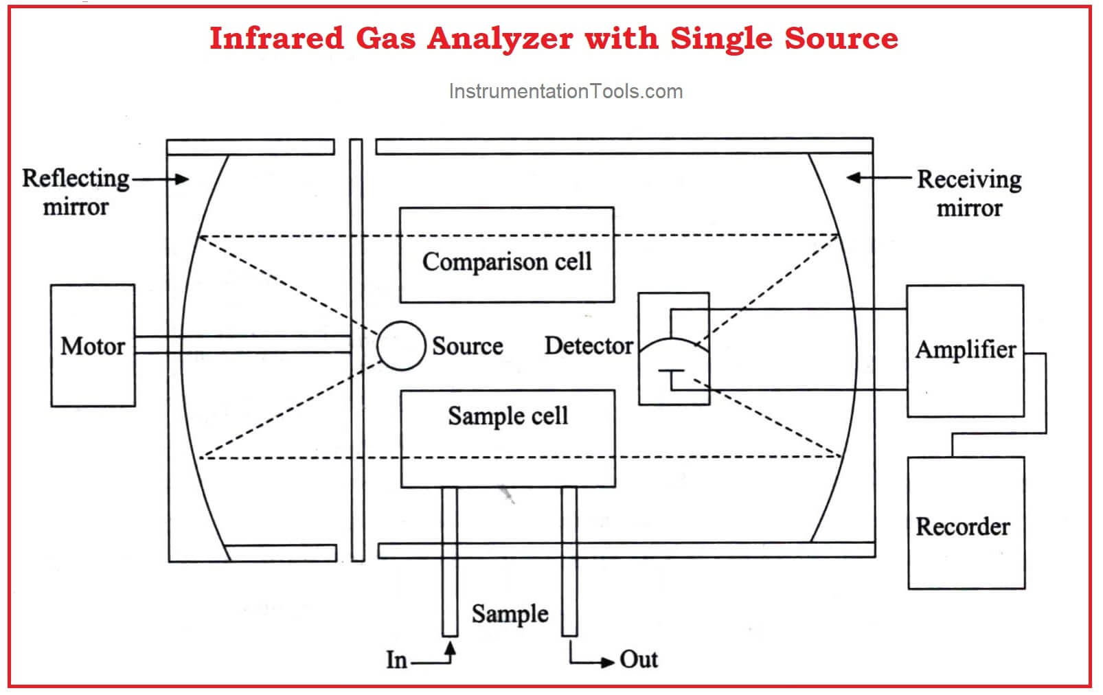
Similar sources are eliminated which may cause minor differences.

 Infrared analyzers can be used to analyze independently the CO, CO2, NOx, SOx, etc. that are present in the flue gas of a thermal power plant.

Don't Miss Our Updates
Be the first to get exclusive content straight to your email.
We promise not to spam you. You can unsubscribe at any time.
Invalid email address
You've successfully subscribed !

Continue Reading

Gas Filter Correlation (GFC) Spectroscopy
Humidity Sensing Absorption Hydrometer Principle
Dual-beam Non-dispersive Analyzer
Humidity calculator
Total Organic Carbon Analyzers Questions and Answers
Hair Hydrometer Principle
Share This Article
Facebook Whatsapp Whatsapp LinkedIn Copy Link
Share
Leave a Comment

Leave a Reply Cancel reply

Your email address will not be published. Required fields are marked *

Stay Connected

128.3kFollowersLike
69.1kFollowersFollow
210kSubscribersSubscribe
38kFollowersFollow

Categories

Explore More

How to Calibrate pH Electrode?
Ammonia Gas Detector Working Principle and Calibration
Luft detector Principle
Turbidity Analyzer Working Principle
Conductivity Analyzers Interview Questions & Answers
Working Principle of Gas chromatograph
Moisture Calculator
Dissolved Oxygen Analyzer Interview Questions & Answers

Keep Learning

what-is-gas-metering-system

What is Gas Metering System?

Industrial Gases

Questions and Answers on Gas

What is Gas Chromatography

What is Gas Chromatography?

Thermal Conductivity Detector (TCD)

Thermal Conductivity Detector (TCD) Principle

Analytical Instrumentation Engineering Projects

Top 100 Analytical Instrumentation Engineering Projects

Sling Psychrometer Principle

Sling Psychrometer Principle

Suspended Particulate Matter

Basics of Suspended Particulate Matter (SPM) Analyzers

Technologies for Oxygen Gas Measurement

Technologies for Oxygen Gas Measurement

Learn More

Optimal Control Systems

Parameter Optimization : Servomechanims

Industrial Control Systems Security

Comparing ICS and IT Systems Security

Formula for Linear mA to Square root mA conversion

Hall Effect Transducers Objective Questions

Hall Effect Transducers Objective Questions

IACS Network

Remote Connectivity to Industrial Automation Systems

High-pressure Service Level Transmitters Misunderstood Zero Drifts

High-pressure Service Level Transmitters Misunderstood Zero Drifts

Cable Bending Radius

What is Cable Bending Radius? – Definition & Calculation

Difference between LVDT and RVDT

Difference between LVDT and RVDT?

Menu

  • About
  • Privacy Policy
  • Copyright

Quick Links

  • Learn PLC
  • Helping Hand
  • Part Time Job

YouTube Subscribe

Follow US
All rights reserved. Reproduction in whole or in part without written permission is prohibited.
Welcome Back!

Sign in to your account

Username or Email Address
Password

Lost your password?