When you work in an instrumentation system, you will find that a document called P&ID is always in use. P&ID (piping and instrumentation diagram) is a document that shows the plant layout of instruments and pipes co-related with each other. Due to this, we get an overall idea of the whole process.
What is a Legend?
In the P&ID drawing, there is a column that denotes symbols of various types of instruments. This is called a legend. Whenever we design a drawing document, it is necessary that we understand legends.
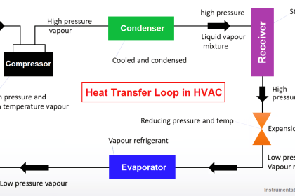
Refer to the below image for understanding. You can see that various types of symbols representing mechanical, instrumental, and electrical objects are represented here. Simply, consider that you are designing a cartoon drawing. There are five types of cartoons, used multiple times in the drawing. A legend here means it will depict the symbols of each of the cartoons with their names. This will help identify which type of cartoon is used in a particular position.
Similar to this concept, a legend in instrumentation drawing thus depicts which type of instrument is used in the drawing. Due to this, you can memorize each and every object in the drawing easily as identification becomes easier.
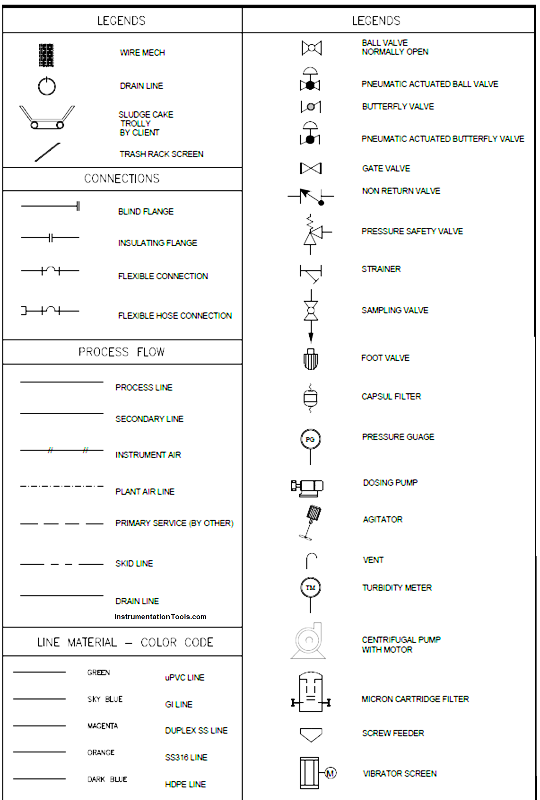
In the figure, you can see that there are various types of symbols like line color, process flow type, connection types, and instruments. When you remember these symbols, you can see that whenever you then read a drawing, you will instantly pick what symbol is used here and why.
Piping and Instrumentation Diagram Example
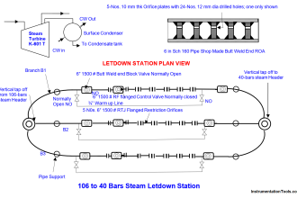
For example, refer to the below image. You can see that a major of two types of symbols – valves (BV) and pressure gauges (PG) are used. These symbols, even if not given a name, will help you identify which instrument is connected in the pipeline. This can help the user understand the flow of the process very easily.
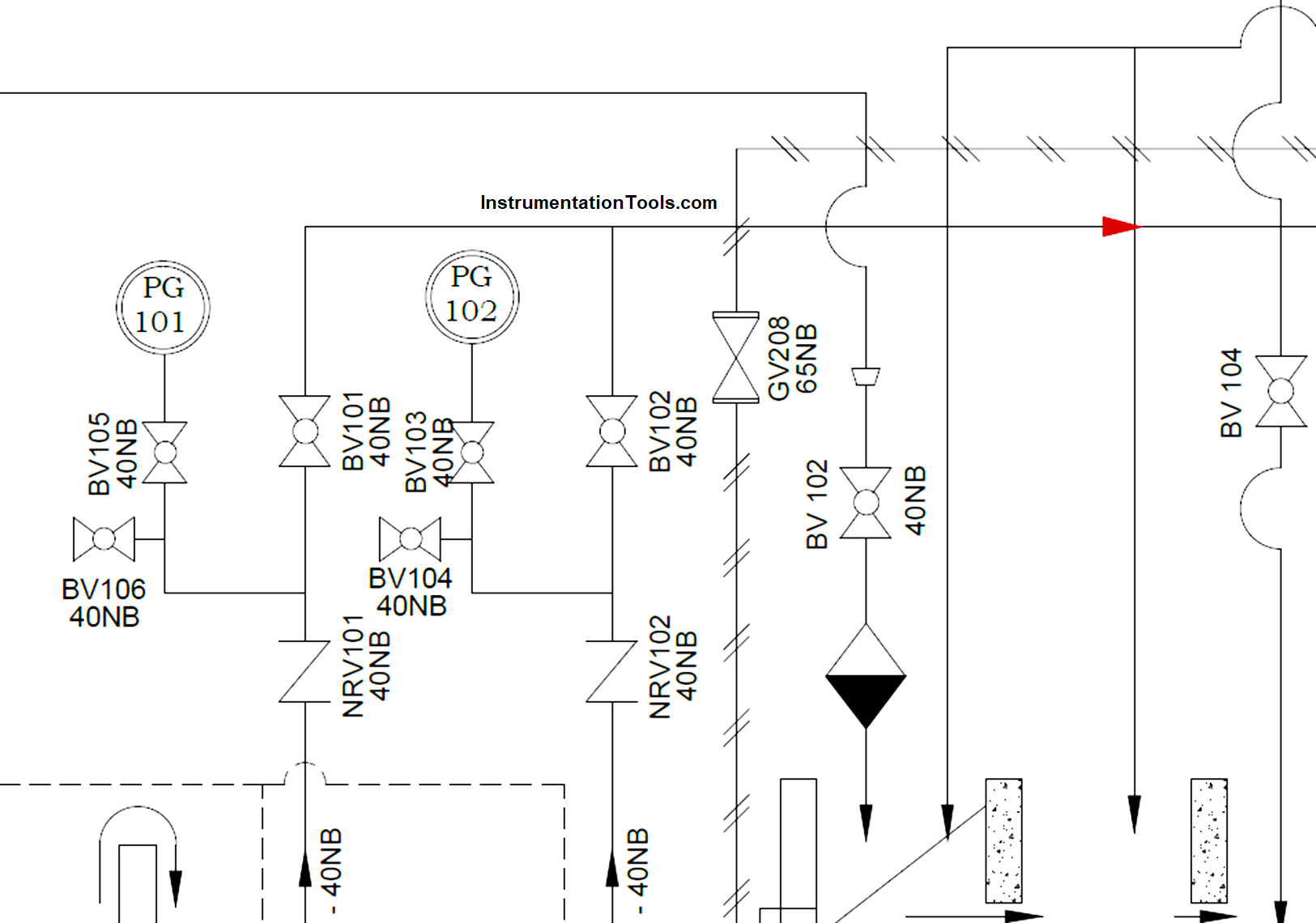
You can find that whenever such drawings have legend charts in them, a user can easily distinguish the difference between drawings. It shows how powerful a legend is in helping engineers design the system. Without a legend, it could be hard for you to figure out exactly what you are looking for.
Leave apart designers, suppose some maintenance engineers are working in a system. When they find any issue, they will, first of all, refer to this document containing legends. This can help them show which connection is done with which instrument. This is important for maintenance workers repairing a system, and operators will know which valve to turn, or which instrument to refer for a reading. If they didn’t know what all of these symbols were, it would make their job extremely difficult to troubleshoot and maintain. So, legends are an extremely important tool in an instrumentation diagram.
Types of Legends
Normally, legends are categorized into the following types of symbols – instruments, valves, pumps, line color, connection types, piping, vessel, and heat exchanger. The shapes in this legend are representative of the functional relationship between piping, instrumentation, and system equipment units.
In this way, we saw the concept of legends in instrument drawings.
If you liked this article, then please subscribe to our YouTube Channel for Instrumentation, Electrical, PLC, and SCADA video tutorials.
You can also follow us on Facebook and Twitter to receive daily updates.
Read Next:
- Instrument Numbering Philosophy
- Identify Process Variables in P&ID
- Difference between PFD and P&ID
- Hydraulic and Pneumatic P&ID Diagrams
- Piping and Instrumentation Diagram (P&ID)