Inst ToolsInst ToolsInst Tools
  • Courses
  • Automation
    • PLC
    • Control System
    • Safety System
    • Communication
    • Fire & Gas System
  • Instrumentation
    • Design
    • Pressure
    • Temperature
    • Flow
    • Level
    • Vibration
    • Analyzer
    • Control Valve
    • Switch
    • Calibration
    • Erection & Commissioning
  • Interview
    • Instrumentation
    • Electrical
    • Electronics
    • Practical
  • Q&A
    • Instrumentation
    • Control System
    • Electrical
    • Electronics
    • Analog Electronics
    • Digital Electronics
    • Power Electronics
    • Microprocessor
  • Request
Search
  • Books
  • Software
  • Projects
  • Process
  • Tools
  • Basics
  • Formula
  • Power Plant
  • Root Cause Analysis
  • Electrical Basics
  • Animation
  • Standards
  • 4-20 mA Course
  • Siemens PLC Course
Reading: Float level switch Principle
Share
Notification Show More
Font ResizerAa
Inst ToolsInst Tools
Font ResizerAa
  • Courses
  • Design
  • PLC
  • Interview
  • Control System
Search
  • Courses
  • Automation
    • PLC
    • Control System
    • Safety System
    • Communication
    • Fire & Gas System
  • Instrumentation
    • Design
    • Pressure
    • Temperature
    • Flow
    • Level
    • Vibration
    • Analyzer
    • Control Valve
    • Switch
    • Calibration
    • Erection & Commissioning
  • Interview
    • Instrumentation
    • Electrical
    • Electronics
    • Practical
  • Q&A
    • Instrumentation
    • Control System
    • Electrical
    • Electronics
    • Analog Electronics
    • Digital Electronics
    • Power Electronics
    • Microprocessor
  • Request
Follow US
All rights reserved. Reproduction in whole or in part without written permission is prohibited.
Inst Tools > Blog > Level Measurement > Float level switch Principle

Float level switch Principle

Last updated: April 24, 2019 3:44 pm
Editorial Staff
Level Measurement Switches
No Comments
Share
2 Min Read
SHARE

Some level switches use a float to sense the level of a liquid surface, actuating an electrical switch by the motion of the float. The electrical schematic symbol for a level switch is actually based on this type of mechanism, with a round “ball” float drawn as the actuating element:

Level Switch Symbols

An example of this technology is a level switch manufactured by Magnetrol, with two such switches shown in the following photograph of a steam boiler. These switches sense water level in the steam drum of the boiler:

Float level switch

Boiler Level Switch

The Magnetrol float switch mechanism uses a mercury tilt bulb, tilted by a magnet’s attraction to a steel rod lifted into position by a float.

The float directly senses liquid level, positioning the steel rod either closer to or farther away from the magnet. If the rod comes close enough to the magnet, the mercury bottle tilts to change the switch’s electrical status:

Magnetrol float switch working

A feature of this design is complete isolation between the electrical components and the “wet” components sensing the liquid level.

The steel rod moves inside a non-magnetic metal tube, with the tube sealing process fluid pressure from escape while still allowing the magnetic tilt switch to sense float position.

Simpler float switch designs also exist for direct installation in open (vented) process vessels, resembling the float valve assembly on a water-flush toilet.

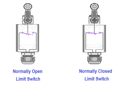
Any “limit” style switching element will work here, including inductive proximity switches, to sense the float’s position in an environment where no isolation need exist between the switch and the process fluid(s):Float Switch Operation

Articles You May Like :

What is a Limit Switch ?

Switch Types

Interface Level Guide

Cable Float Level Switch

DP Level Transmitter Errors

Don't Miss Our Updates
Be the first to get exclusive content straight to your email.
We promise not to spam you. You can unsubscribe at any time.
Invalid email address
You've successfully subscribed !

Continue Reading

Servo Tank Gauges Working Principle
How to Calibrate Temperature Switch? – Instrument Basics
Tilt Level Switch Working Animation
Limit Switch Animation
Bubbler Liquid Level Transmitter Calculation
Guided-Wave Radar Instruments Diagnostics
Share This Article
Facebook Whatsapp Whatsapp LinkedIn Copy Link
Share
Leave a Comment

Leave a Reply Cancel reply

Your email address will not be published. Required fields are marked *

Stay Connected

128.3kFollowersLike
69.1kFollowersFollow
210kSubscribersSubscribe
38kFollowersFollow

Categories

Explore More

Hybrid Level Measurement Principle, Selection, Installation, Limitations and Calibration
Magnetostrictive Tank Gauging (MTG)
Electromagnetic and Conductive limit switches Principle
Ultrasonic Level Transmitter Working Principle
Interface Level Measurement Selection Guide
Ultrasonic Level Transmitter Animation
Level Gauges Objective Questions and Answers – Instrumentation
Closed tank DP Level Transmitter with wet leg elevation zero remote mount Calibration

Keep Learning

Open Tank DP Level Measurement

Open Tank DP Level Transmitter Calculations

Float level gauge Principle

Float Type Level Indicator Principle

Differential Pressure Measurement

Basics of Differential Pressure Level Transmitters

Level Instruments

Level Instruments General Specifications

Which instrument is at fault in this system

Which Instrument is at Fault in this System?

Level-Transmitters-Animation

Level Transmitter Animation

Questions on Level Switches

Questions on Level Switches

Proximity Switch PNP Type Working Animation

Proximity switches Circuit Diagram Operation

Learn More

Power Electronics Objective Questions

Thyristor Rating Objective Questions and Answers

Role of Flow Meters in a Laboratory

Role of Flow Meters in a Laboratory

Basic Pneumatic System

Pneumatic Handbook

Selecting a SIS or SIL Level

Importance of Safety Integrity Level

Schneider Electric Modicon M340 PAC

PLC vs PAC – Understanding the Key Differences and Similarities

What is Data Acquisition

What is Data Acquisition? – Elements and Components

Why have been limits imposed on the frequency ratio for thermowells?

IEC 60909 and IEC 61363 for Short Circuit

Difference Between IEC 60909 and IEC 61363 for Short Circuit

Menu

  • About
  • Privacy Policy
  • Copyright

Quick Links

  • Learn PLC
  • Helping Hand
  • Part Time Job

YouTube Subscribe

Follow US
All rights reserved. Reproduction in whole or in part without written permission is prohibited.
Welcome Back!

Sign in to your account

Username or Email Address
Password

Lost your password?