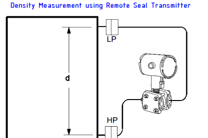
The DP level transmitter installed below HP tapping point with wet leg.Schematic Diagram of a Closed tank DP Level Transmitter with wet leg elevation zero remote mount Calibration
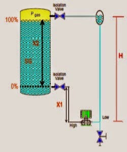 |
| Closed tank DP Level Transmitter with wet leg elevation zero remote mount Calibration |
Formulas:
Min range = (SG x X1) – (SG x H)
Max range = [(SGxX1) + (SGxX2)] – (SGxH)
Example:
If the height is 1 meter an X1, X2 is 3 meters and a height H is 4.5 meters, in the tank there is cairin which has a density of 1 g / cm3, what is the range of calibration on the transmitter?
SG = 1
Min range = P High – P Low
= (SG x X1) – (SG x H)
= (1 x 1) – (1 x 4.5)
= 1 -4.5
= – 3.5 mH 2 O
Max range = P High – P Low
= [(SGxX1) + (SGxX2)] – (SGxH)
= [(1×1) + (1×2) – (1×4,5)
= 4 to 4.5
= -0.5 MH 2 O
The transmitter Range = -3.5 to -0.5 mH 2 O


Easy to learn.. but all students needs to calculate the range by themselves.. beacause one printing mistake is there.
Hi, Please elaborate the details.
In the max range calculation x2 height is mentioned as 2…Our actual range is 3…So let to be corrected in the value
very useful