Although the scope of the document is about fixed installed measuring instruments, manual measurements should be at least discussed briefly. Manual measurements are still quite often used as they are perceived as ‘low cost’ (at least initial), do not require cabling or power and are often used for during commissioning, or verification of installed instrumentation.
Manual Level Measurement
There are three mains manual measurement principles used:
- tape, ruler or dip stick
- sight glass
- portable electronic.
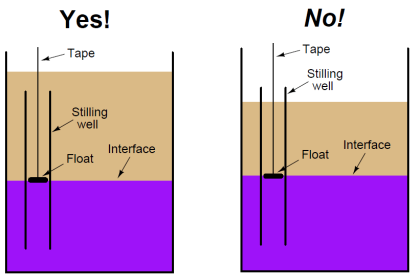
Both of these manual methods make use of a graduated measurement tape, ruler or dipstick, to read the level and/or interface.
Tape, ruler and dipstick
This measurement is typically used on large tanks.
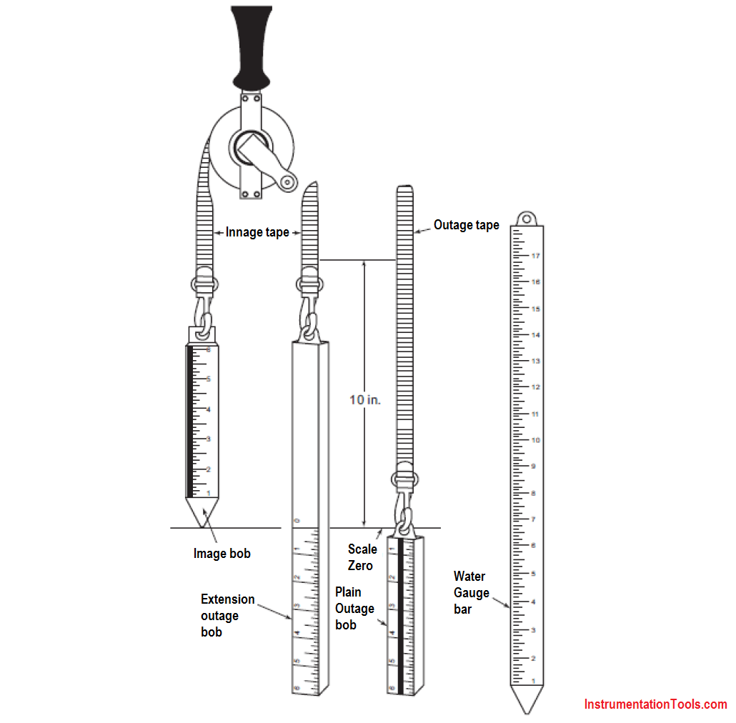
Figure – Typical gauge tapes, bobs and a water gauge bar (Source: API MPMS Ch. 3.1A)
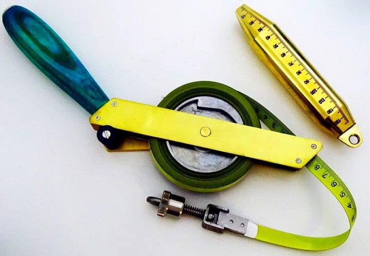
Figure – Photo of typical dip tape as use on bulk storage tanks
Image Courtesy : Rigana
A ruler or dipstick is typically used for relative small tanks. A practical limit is 2 to 3 metres height max. In some area’s/countries also so called ‘slip tube’ gauges are used for on LPG rail tankers.
NFPA 58 describes slip tube gauge as a “A variable liquid level gauge in which a relatively small positive shutoff valve is located at the outside end of a straight tube, normally installed vertically, that communicates with the container interior.” A slip tube is basically a ‘dip stick’.
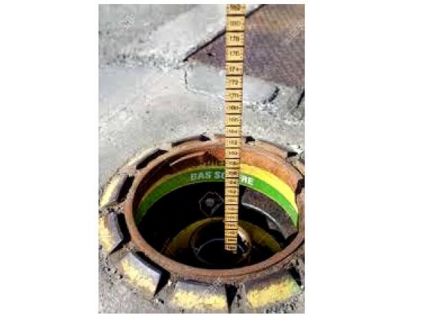
Figure – Example of dip opening of foreground station (petrol station)
On clear liquids and very light products which easily evaporate, including water, often a coloring paste is used. The paste changes color when in direct contact with the liquid.
For water detection which is often called ‘water‐finding’ rule to detect a level is recommended. Water finding rules are typically made of brass with alternating transparent plastic sections, which allows seeing where the paste has discolored when measuring water in opaque oils
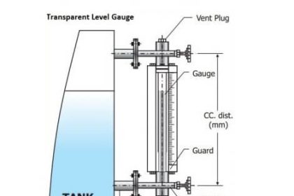
Sight glass
For closed tanks, and products which are toxic, easily evaporate or are flammable, often a sight glass is used.
The sight glass is typically installed as part of a ‘chamber/cage’. It can either be a transparent piece of piping or a metal enclosure with typically a hardened flat glass view pane.
The tank connections often have block valves, which allow maintenance on the sight glass and sight glass body. Some sight glass designs also incorporate drain valves which allows cleaning (‘flush’) the system.
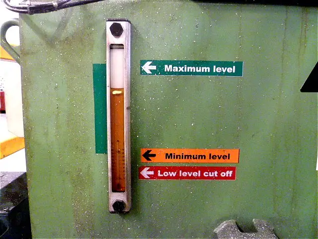
Figure – Sight glass on fuel tank
Reflex gauges are a special form of sight glass gauges, and use optical refraction and reflection for an improved visibility of interfaces in and between vapour/gas and liquid zones.
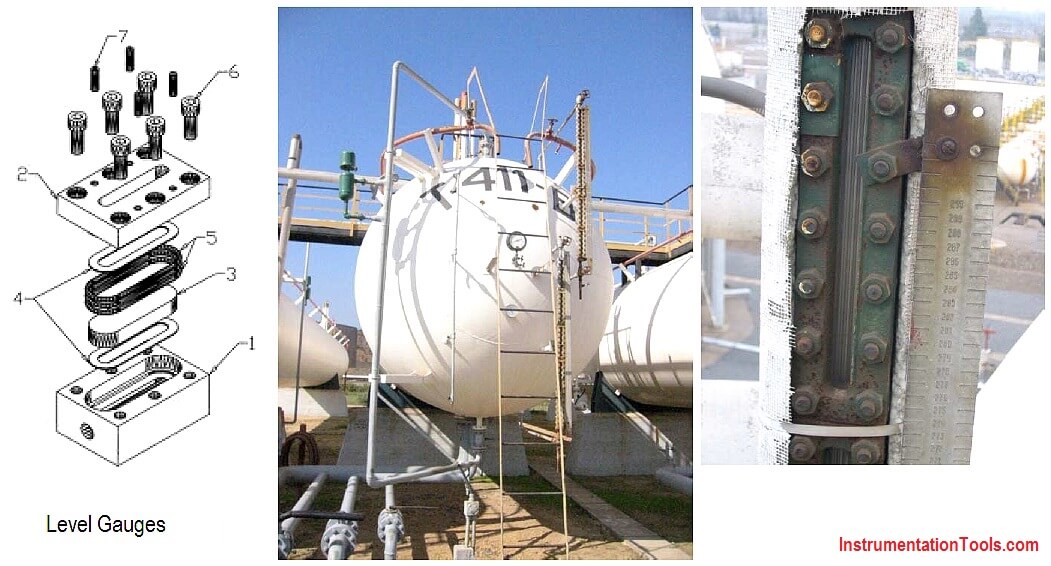
Figure (Left) Example of sight glass construction for pressurized application
Figure (Middle) Sight glass installed on LPG horizontal bullet tank
Figure (Right) High pressure sight glass with graduated scale
Is some specific areas and equipment (steam generators, boilers, power generation), the use of sight glass type level gauges may also be mandatory to fulfill the design code (e.g. ASME I).
Sight glass may also be useful where direct vision of the fluid is relevant.
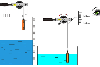
Portable electronic gauging
Portable electronic gauging can measure the level of ullage and the oil–water interface. Portable electronic gauging is suitable for open and closed applications. Closed gauging operations will generally require the portable electronic gauging to be used in conjunction with a compatible vapour lock valve.
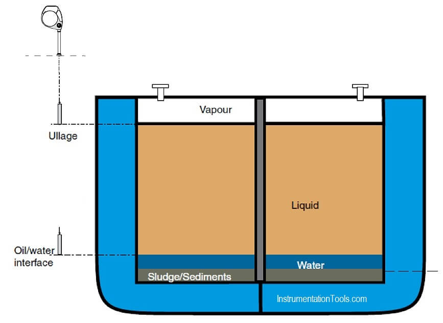
Figure – Portable electronic gauging system with vapour lock valve
Representative measurements of the temperature of the tank contents may also be measured with the portable electronic gauging. This temperature measurement permits to convert the observed volume to a standard volume measurement.
Limitations
Tape, ruler and dipstick
Tape, ruler or dipstick can only be used when the tank is not pressurized and the tank contents are considered to be safe (i.e. not toxic, dangerous and do not pose an environmental issue).
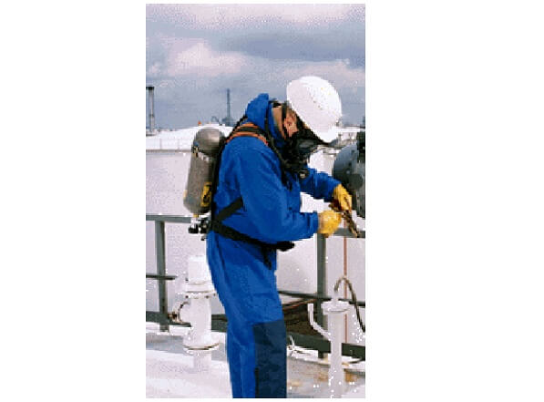
Figure – Necessary safety precautions (PPE) on toxic products
Sight glass
Sight glasses cannot be used for tanks containing sediment or solids, as the connection might become blocked.
Use of sight glasses can be considered for interface measurement also, provided the interface layer is clearly visible.
Sight glass installation is also possible on pressurized tanks but sometimes perceived as a safety risk.
On tanks which also contain solids, the reading of the sight glass can be unreliable as result of blockage. For these applications strict procedures for periodic flushing the sight glass and connections should be considered.
Sight glass systems have the limitation of where the level can be between glasses and in the ‘brass’ area and hence it is difficult to understand where the level is.
Sight glasses require regular maintenance and cleaning. The presence of some hydrocarbon liquids can cause staining and this can make it difficult to ascertain where the true level actually is placed.
Portable electronic gauging
Safety and environmental regulations may restrict tank gauging operations which can result in the release of hydrocarbons or other volatile organic compounds into the atmosphere. In these circumstances, it will not normally be feasible to use traditional open gauging procedures via an open gauge hatch or gauging access point.
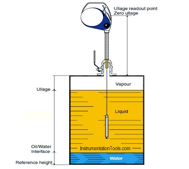
Figure – Portable electronic gauging system with vapour lock valve
Selection
For all toxic, pressurized and dangerous products, ‘closed’ solutions are preferred.
If manual methods are to be used, the safe use should be covered by procedures and formal training.
Calibration and configuration
For applications where the accuracy is of importance, the graduated scale on tape, dip stick or sight glass can be calibrated.
It is important to realize that it is always critical to use the correct datum point on the particular tank. This datum point can be a ‘dip’ plate on the bottom or a clear marked mechanical provision on or in the tank nozzle.
Sight glasses can be adjusted by shifting the graduated scale.
The portable electronic gauging sensor is calibrated once at the factory and does not require subsequent calibration.
Source : International Association of Oil & Gas Producers
Acknowledgements : IOGP Instrumentation and Automaton Standards Subcommittee (IASSC), BG Group, BP, Endress + Hauser, Emerson, Honeywell, Krohne, Petrobras, PETRONAS Carigali Sdn Bhd, Repsol, Siemens, Statoil, Total, Vega, Yokogawa.