When choosing a control valve for a process, there are many things that must be considered, including the valve’s flow characteristic, its size, noise, the potential for cavitation or flashing damage, body and trim materials, actuator size and type, and its dynamic response to changes in the control signal.
The selection primarily depends upon the application and the pressure and temperature conditions.
How to Choose a Control Valve?
There are many types of valves available, each having its advantages and limitations. The basic requirements and selection depend on their ability to perform specific functions such as:
- Ability to throttle or control the rate of flow.
- Lack of turbulence or resistance to flow when fully open as turbulence reduces head pressure.
- Quick opening and closing mechanism – rapid response is many times needed in an emergency or for safety.
- Tight shut-off prevents leaks against high pressure.
- Ability to allow flow in one direction only – prevents return.
- Opening at a pre-set pressure – procedure control to prevent equipment damage
- Ability to handle abrasive fluids – hardened material prevents rapid wear.
This article discusses basic valve types, types of actuators, control actions, types of positioners.
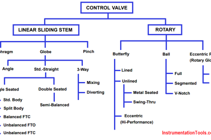
Based on control actions, they are linear motion and rotary motion
Linear motion
Linear valves, also known as multi-turn valves, have a sliding-stem design that pushes a closure element into an open or closed position. Common valves are globe valves, gate valves.
Rotary motion
Rotary motion is also known as quarter-turn valves. Quarter turn valves will be in their fully open or fully closed state (0°) after a 90° turn of the stem.
Their operation is much quicker than linear motion valves. Common are ball valves, butterfly valves.
Basic Valve Types
Valves are available with a wide variety of valve bodies in various styles, materials, connections, and sizes. Selection is primarily dependent on the service conditions, the task, and the load characteristics of the application.
Read:
The most common types are ball valves, butterfly valves, globe valves, and gate valves.
Ball Valves
Ball valves are quick opening valves that give a tight shutoff. When fully open, a ball valve creates little turbulence or resistance to flow.

Ball valves are considered high recovery valves, having a low-pressure drop and relatively high flow capacity.
Best Suited Control:
- Quick opening,
- linear
Uses:
- Fully open/closed,
- limited-throttling
- Higher temperature fluids Applications
Advantages:
- Low cost
- High flow capacity
- High pressure/temperature capabilities
- Low leakage and maintenance
- Tight sealing with low torque
- Easy quarter-turn operation.
Disadvantages:
- Limited throttling characteristics
- Prone to cavitation.
Butterfly Valves
Butterfly valves consist of a disc attached to a shaft with bearings used to facilitate rotation. These are considered high recovery valves since only the disc obstructs the valve flow path. The flow capacity is relatively high and the pressure drop across the valve is relatively low.

The butterfly valves are used for limited throttling where a tight shut off is not required. When fully open, the butterfly creates little turbulence or resistance to flow.
Best suited control:
- Linear,
- Equal percentage
Uses:
- Fully open/closed or throttling services
- Frequent operation
- Applications where a small pressure drop is desired
Applications:
- Most economical for large lines in chemical services, water treatment, and fire protection systems.
- Due to the valve design, incorporating a small face-to-face dimension and lower weight than most valve types,
- The butterfly valve is an economical choice for larger line sizes (i.e. 8″ and above).
Advantages:
- Low cost, maintenance and light weight, so need less support
- High capacity
- Good flow control
- Low-pressure drop
Disadvantages:
- High torque required for control
- Prone to cavitation at lower flows
Generally not rated as bubble-tight, and the cavities and leak paths around the disc stem are potential entrapments for fluids and slurries.
Globe Valves
Globe valves consist of a movable disk-type element and a stationary ring seat in a generally spherical body. The valve stem moves a globe plug relative to the valve seat. The globe plug can be at any position between fully opened and fully closed to control flow through the valve.
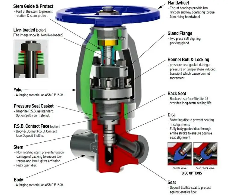
Image Courtesy: Flowone
The globe and seat construction gives the valve good flow regulation characteristics. Turbulent flow past the seat and plug, when the valve is open, results in a relatively high-pressure drop, limited flow capacity, and low recovery.
Best suited control:
- Linear and
- Equal percentage
Uses:
Applications requiring: a)Precise flow regulation
- Frequent and wide throttling operation
- Suited to very high pressure drops Applications
- Suitable for most liquids, vapors, gases, corrosive substances
- Pressure limitations are relatively high, ranging from 1480 to 1500 psi, dependent on materials of construction, size, and temperature.
- Minimum and maximum temperatures are also very broad ranging from -425°F to 1100°F, depending again on the materials of construction.
Advantages:
- Efficient and precise throttling
- Accurate flow control
Disadvantages:
- Low recovery and a relatively low coefficient of flow (Cv).
- High-pressure drop, higher pump capacity, and system wear.
- More expensive than other valves
- The sealing device is a plug that offers limited shut-off capabilities, not always meeting bubble-tight requirements.
Gate Valves
Gate valves use the linear type of stem motion for the opening and closing of a valve. These valves use parallel or wedge-shaped discs as closure members that provide tight sealing.

Best suited control:
- Quick Opening
Uses:
- Fully open/closed, non-throttling
- Infrequent operation
- Minimal fluid trapping in line
Applications:
- Suitable for oil, gas, air, heavy liquids, steam, non-condensing gases, abrasive and corrosive liquids
Advantages:
- High capacity
- Tight shutoff
- Low cost
- Little resistance to flow.
Disadvantages:
- Poor control
- Cavitate at low-pressure drops
- Cannot be used for throttling
Read:
- Different Valve Types
- Types of Check Valves
- Introduction to Valves
- Control Valve Trim
- Parts of Control Valves
Actuators
A valve actuator is a device that produces force to open or close the valve utilizing a power source.
Type of Actuators
Two types of actuators are common:
- Pneumatic and
- Electric actuators.
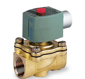
Pneumatic:
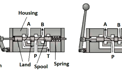
Pneumatic actuators utilize an air signal from an external control device to create a control action via a positioner or a solenoid. These are commonly available in two main forms: piston actuators and diaphragm actuators.
Piston Actuators
Piston actuators are generally used where the stroke of a diaphragm actuator would be too short or the thrust is too small.
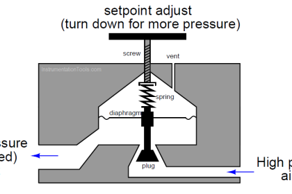
Diaphragm Actuators
Diaphragm actuators have compressed air applied to a flexible membrane called the diaphragm. These types of actuators are single-acting, in that air is only supplied to one side of the diaphragm, and they can be either direct-acting (spring-to-retract) or reverse acting (spring-to-extend).
Control Action:
In pneumatic operated valve, there are two control actions possible:
- “Air (or current) to open” – The flow restriction decreases with increased control signal value.
- “Air (or current) to close” – The flow restriction increases with increased control signal value.
There can also be a failure in safety modes:
- Air (or control signal) failure to close” – On failure of compressed air to the actuator, the valve closes under spring pressure.
- Air (or control signal) failure to open” – On failure of compressed air to the actuator, the valve opens under spring pressure.
Read:
Advantages of Pneumatic Actuators
The biggest advantage of pneumatic actuators is their fail-safe action. By design of the compressed spring, the engineer can determine if the valve will fail closed or open, depending on the safety of the process
Electric:
Electric actuators are motor-driven devices that utilize an electrical input signal to generate a motor shaft rotation. This rotation is, in turn, translated by the unit’s linkage into a linear motion, which drives the valve stem and plug assembly for process variable modulation.
Actuators utilize two types of motors
A step motor uses gears with increments in the range of 5,000 to 10,000 at 90-degree rotation for accurate positioning at lower speeds.
Servos, by definition, are closed-loop and provide superior performance at high speeds, but at a higher cost.
Advantages:
- Low operating cost. Controllers and drivers low voltage circuitry consumes power to a far lesser degree.
- Response time is essentially instantaneous.
- Provide precise control and positioning in comparison to pneumatic actuators.
Disadvantages
- The primary disadvantage of an electric actuator is that, should a power failure occur, the valve remains in the last position and the fail-safe position cannot be obtained easily unless there is a convenient source of stored electrical energy.
- Higher cost than pneumatic actuators.
- Generally not recommended for flammable atmospheres.
Read:
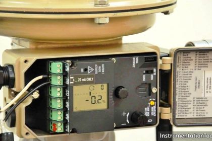
Valve Positioner
A valve positioner is a control device designed to impart sensitivity to the valve and to ensure accurate positioning as dictated by a control signal.
The addition of positioner can correct many variations including changes in packing friction due to dirt, corrosion, or lack of lubrication, variations in dynamic forces of process.
A positioner may be used as a signal amplifier or booster. It accepts a low-pressure air control signal and, by using its own higher pressure input, multiplies this to provide a higher pressure output air signal to the actuator diaphragm.

When should a positioner be fitted:
A positioner should be considered in the following circumstances:
- To linearize a non-linear actuator;
- When controlling with wide throttling range
- To speed up the valve response.
- Positioner allows split ranging the controller signal between more than one valve.
- Process parameters such as pressure, temp, the flow have to be closely controlled.
Read:
- Control Valve Positioners
- Testing of Valve Positioners
- Pneumatic Valve Positioner
- Valve Positioner Schematic


Diapharm actuators are also double acting actuators.