The Cable type Float Level Switch is made from chemical resistant polypropylene. It is durable, low-cost,and specially designed to assist with long range and multiple point level detection in liquids. It is also suitable for tanks containing pumps and granular solutions.
The Cable Float Level Switch is a structured by using either micro switches, proximity switches or reed switches to control the contact. It’s user-friendly design is ideal for level measurement.
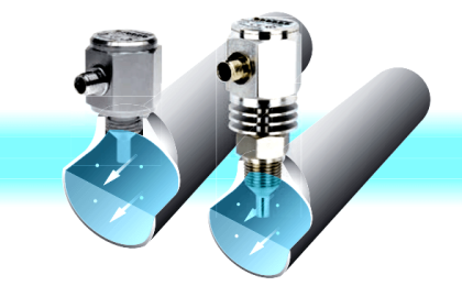
The switches will transmit an ON or OFF contact signal output when the float rises and turns upwards. The switch contains a metal ball that can slide as the float position changes. The change in contact signal is used to detect the level.
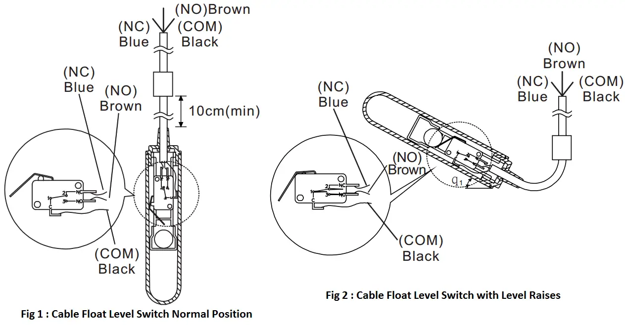
Cable Float Level Switch using Micro Switch
When the float hasn’t contacted the liquid, the blue and black wires are in an open state and the contact mode will be NC.
When the liquid level rises and lifts the float until it reaches the actuation angle, the brown and black wires will be in an open state and the contact mode will be NO.
For different water or solution temperatures, different float materials are available for selection. Plastic and stainless steel switches are the most common. The cable float level switch can not only can be used in clear liquids but also can be used in granular liquids.
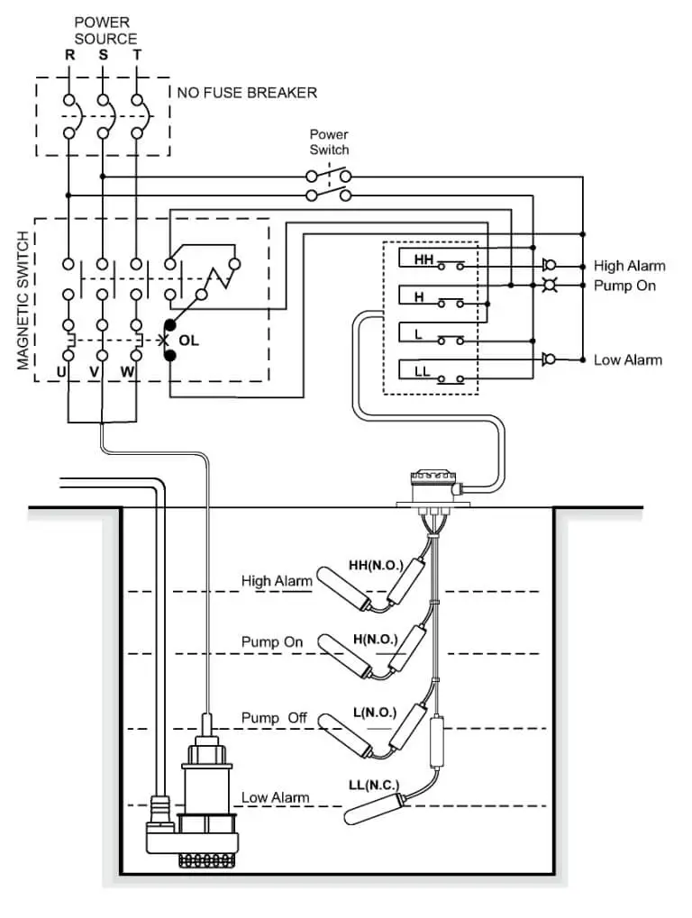
Long-distance detection points and multi-point contacts are also available. Cable float level switches can be applied in all water management, petrochemical, chemical industries.
Other uses include air-conditioner systems, drainage systems, most tanks, or containers with level switch requirements.
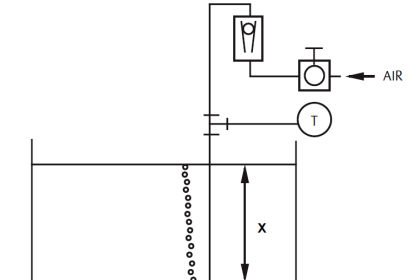
Installation Techniques:
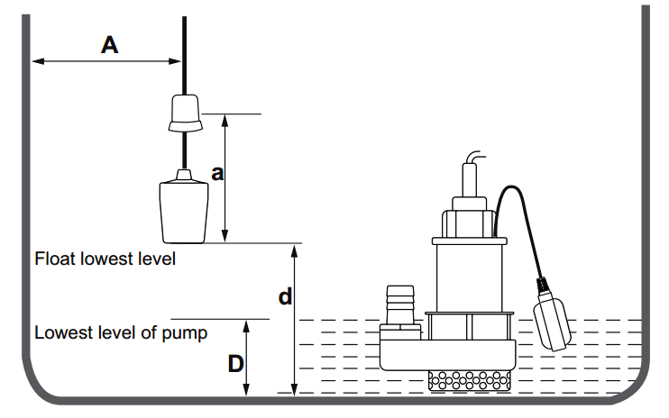
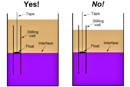
The float’s action length (a) must be shorter than the distance between the wall and the cable (A) ; if not,it will not function accurately.
The lowest float level (d) must be higher than the lowest water level of the pump (D).
Application:
Source: FineTek
Read Next:
- Differential Pressure Switch
- Micro Sensors Objective Question
- How to Select a Rotameter
- All Types of Level Switches
- Level Instruments Specifications


los mejores son los que tienen una ampolla de Mercurio, el metal líquido a temeratura ambiente, que no es tan tóxico como dicen los ignorantes.
Translated from spanish to english: The best are those who have a blister of Mercury, the liquid metal to ambient temeratura, which is not as toxic as the ignorant say