Introduction
Application
Using typical smart or conventional products all of the following must be considered:
- The specific gravity of the process;
- Precise location of 0% and 100%;
- Specific gravity of the capillary fill fluid or sealing liquid (for impulse tubing);
- Vertical height of capillary or impulse piping;
- Exact orientation of the transmitter to the vessel;
- Vertical distance between the flanges.
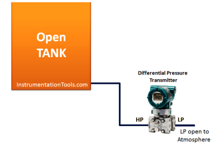
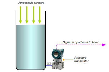
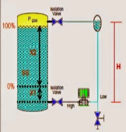
Depending on the application, the vessel may be open (referencing atmosphere), or closed (under some blanket pressure).
Suppression is positive pressure created on the high side of the transmitter typically due to a zero point above the transmitter. It is normally employed in an open vessel referencing atmosphere. This is a positive pressure equal to the vertical distance between the 0% point and the transmitter times the specific gravity of the liquid.
Elevation/suppression distance almost never agrees with the P&ID because actual piping (or remote seal capillaries) do not form exacting angles in the field. In most cases, the precise vertical height is not known until the unit is installed.
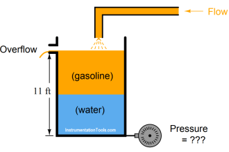
0% = H – L
(4.5 x 0.8) – (15 x 0.8)
3.6 – 12 = -8.4 mH2O (-28 inH2O)
100% = H – L
(4.5 x 0.8) + (10.5 x 0.9) – (15 x 0.8)
3.6 + 9.45 – 12 = 1.05 mH2O (3.5 inH2O)
The calibration range is:
-8.4 to 1.05 mH2O (-28 to 3.5 inH2O)
The information required to perform the calculation is not readily available. It exists in vendors instruction manuals, P&ID’s, but not until the unit is actually installed will all the variables be known because the process piping and capillaries do not form exacting angles in the field.
Solution
DPharp has a smart level setup feature that eliminates the need for elevation/suppression calculations, making set up quick and painless.
Calibration is accomplished by simply following these four steps:
- Span the transmitter to the process, height * specific gravity of 0 to 9.45 mH2O (0 to 31.5 inH2O) using the BT200 in C21: LRV andC22: HRV.
- Install to the prss using either capillaries or impulse tubing.
- Bring the process to a zero (4mA) condition.
- Through the BT200 execute H10: Auto LRV in the H: AUTO SET menu.
DPharp will calculate the total elevation/suppression and automatically setup the device for that installation. It will even correct the values in software at C21 LRV -28 and C22 HRV 3.5 so the customer can print and record the actual configuration for their maintenance documents.
But what if I cannot bring my process to zero? I have installed the unit, fluid is now in the tank, and the output of the transmitter does not agree with my sight glass. What do I do?
Most transmitters can only make adjustments at 0% or 100%. DPharp can make adjustments anywhere with full elevation or suppression. Once the transmitter is programmed with the correct span, all that is needed is a known point in the process (usually provided by the sight glass.) The output can be adjusted in one of two ways.
- Simply adjust the encoder on the DPharp until the output reaches the known point. In figure 1, the output would be adjusted to 60%.
- The correct value can be entered into J10: Zero Adj. In the case of this example, the proper output value of 60% would be entered. The amount of deviation can be viewed in J11: Zero Dev.
DPharp’s digital sensing technology makes this possible. With analog sensing technologies (like capacitance sensors), range changes often necessitate a re-calibration or a trimming of the A/D converter to achieve specified performance. The digital DPharp sensor has no A/D converter, no trimming is necessary. The new range is guaranteed to perform within specification.
Notes
- In level measurement, it is important to maintain a consistent reference pressure. On a closed tank system, this is most efficiently achieved by the use of remote seals and capillary systems.
- It is important to note that the span is to be calculated on process height x specific gravity of the process fluid, and will not necessarily agree with the physical height.
- Output will be linear to the level, regardless of fluid or blanketing system.
- Use of remote seals eliminates problems such as condensation in impulse piping, the requirement for maintenance of condensate pots and fill fluid leaking into the process.
Main Features of DPharp Transmitter
EJA110A Digital Solution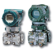
- Best-in-class performance
- ±0.03% Overpressure calibration protection
- ±0.1% per 5 years long term stability
- 100:1 turndown
- ±0.065% accuracy
EJX110A Premium Value
- ±0.1% per 10 years long term stability
- 200:1 turndown
- Best-in-class high accuracy, 0.04%
- Multi-sensing output
- Multi-variable transmitter as EJX family line-up
- Safety as standard (IEC 61508)
Also Read: Calibration of DP Level Transmitter with Remote Seals


Thanks
thank you.
Very nice thank you. Do you have a course about pressure devices and instrumentation. And p&id.