Inst ToolsInst ToolsInst Tools
  • Courses
  • Automation
    • PLC
    • Control System
    • Safety System
    • Communication
    • Fire & Gas System
  • Instrumentation
    • Design
    • Pressure
    • Temperature
    • Flow
    • Level
    • Vibration
    • Analyzer
    • Control Valve
    • Switch
    • Calibration
    • Erection & Commissioning
  • Interview
    • Instrumentation
    • Electrical
    • Electronics
    • Practical
  • Q&A
    • Instrumentation
    • Control System
    • Electrical
    • Electronics
    • Analog Electronics
    • Digital Electronics
    • Power Electronics
    • Microprocessor
Search
  • Books
  • Software
  • Projects
  • Process
  • Tools
  • Basics
  • Formula
  • Power Plant
  • Root Cause Analysis
  • Electrical Basics
  • Animation
  • Standards
  • 4-20 mA Course
  • Siemens PLC Course
Reading: What is a Paddle Wheel Flow Meter?
Share
Notification Show More
Font ResizerAa
Inst ToolsInst Tools
Font ResizerAa
  • Courses
  • Design
  • PLC
  • Interview
  • Control System
Search
  • Courses
  • Automation
    • PLC
    • Control System
    • Safety System
    • Communication
    • Fire & Gas System
  • Instrumentation
    • Design
    • Pressure
    • Temperature
    • Flow
    • Level
    • Vibration
    • Analyzer
    • Control Valve
    • Switch
    • Calibration
    • Erection & Commissioning
  • Interview
    • Instrumentation
    • Electrical
    • Electronics
    • Practical
  • Q&A
    • Instrumentation
    • Control System
    • Electrical
    • Electronics
    • Analog Electronics
    • Digital Electronics
    • Power Electronics
    • Microprocessor
Follow US
All rights reserved. Reproduction in whole or in part without written permission is prohibited.
Inst Tools > Blog > Flow Measurement > What is a Paddle Wheel Flow Meter?

What is a Paddle Wheel Flow Meter?

A variation of turbine flow measurement is the paddle wheel flow meter, a very inexpensive technology usually in the form of an insertion-type flow sensor.

Last updated: November 2, 2023 6:17 am
Editorial Staff
Flow Measurement
No Comments
Share
4 Min Read
SHARE

A variation on the theme of turbine flow measurement is the paddle wheel flow meter, a very inexpensive technology usually implemented in the form of an insertion-type sensor.

Contents
Paddle Wheel Flow MeterPrinciple of OperationProblems of Flow Meters

In this instrument, a small wheel equipped with “paddles” parallel to the shaft is inserted in the flow stream, with half the wheel shrouded from the flow.

Paddle Wheel Flow Meter

A photograph of a plastic paddle wheel flow meter appears here:

Paddle wheel flow meter principle

A surprisingly sophisticated method of “pickup” for the plastic paddle wheel shown in the photograph uses fiber-optic cables (optional) to send and receive light.

One cable sends a beam of light to the edge of the paddle wheel, and the other cable receives light on the other side of the paddle wheel.

Principle of Operation

As the paddle wheel turns, the paddles alternately block and pass the light beam, resulting in a pulsed light beam at the receiving cable.

The frequency of this pulsing is, of course, directly proportional to volumetric flow rate.

The external ends of the two fiber optic cables appear in this next photograph, ready to connect to a light source and light pulse sensor to convert the paddle wheel’s motion into an electronic signal:

Paddle wheel flow meter sensors

A problem common to all turbine flow meters is that of the turbine “coasting” when the fluid flow suddenly stops.

This is more often a problem in batch processes than continuous processes, where the fluid flow is regularly turned on and shut off.

Problems of Flow Meters

This problem may be minimized by configuring the measurement system to ignore turbine flow meter signals any time the automatic shutoff valve reaches the “shut” position.

This way, when the shutoff valve closes and fluid flow immediately halts, any coasting of the turbine wheel will be irrelevant.

In processes where the fluid flow happens to pulse for reasons other than the control system opening and shutting automatic valves, this problem is more severe.

Another problem common to all turbine flow meters is lubrication of the turbine bearings. Frictionless motion of the turbine wheel is essential for accurate flow measurement, which is a daunting design goal for the flow meter manufacturing engineers.

The problem is not as severe in applications where the process fluid is naturally lubricating (e.g. diesel fuel), but in applications such as natural gas flow where the fluid provides no lubrication to the turbine bearings, external lubrication must be supplied.

This is often a regular maintenance task for instrument technicians: using a hand pump to inject light-weight “turbine oil” into the bearing assemblies of turbine flow meters used in gas service.

Process fluid viscosity is another source of friction for the turbine wheel. Fluids with high viscosity (e.g. heavy oils) will tend to slow down the turbine’s rotation even if the turbine rotates on frictionless bearings.

This effect is especially pronounced at low flow rates, which leads to a minimum linear flow rating for the flow meter: a flow rate below which it refuses to register proportionately to fluid flow rate.

If you liked this article, then please subscribe to our YouTube Channel for Instrumentation, Electrical, PLC, and SCADA video tutorials.

You can also follow us on Facebook and Twitter to receive daily updates.

Read Next:

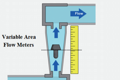
  • Variable Area Flow Meter
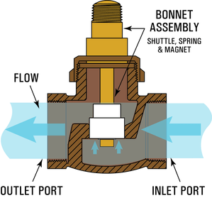
  • Piston Flow Meter Principle
  • Turbine Flow Meter Animation
  • Dall Tube Flow Meter Principle
  • Rotameter Selection Tips
Don't Miss Our Updates
Be the first to get exclusive content straight to your email.
We promise not to spam you. You can unsubscribe at any time.
Invalid email address
You've successfully subscribed !

Continue Reading

What Factors Affect the Stability of Flow Meter Readings?
Difference between Transit time and Doppler Ultrasonic Flow Meter
Ultrasonic Flow Meters Animation
Lobed Impeller Flow Meters Working Principle
What is Differential Pressure Flow Meter?
Measure Flow rate using Level Sensors
Share This Article
Facebook Whatsapp Whatsapp LinkedIn Copy Link
Share
Leave a Comment

Leave a Reply Cancel reply

Your email address will not be published. Required fields are marked *

Stay Connected

128.3kFollowersLike
69.1kFollowersFollow
208kSubscribersSubscribe
38kFollowersFollow

Categories

Explore More

Basics of Venturi Flow Meter
Short Notes on Differential Pressure Flow Meters
What is Integral Flow Orifice Assembly?
Types of Orifice Plates & Orifice Plate Tappings
Orifice Flow Meters: Detailed Specifications
Troubleshooting Ultrasonic Flow Meter Common Problems
Annubar Flow Meter – Principle, Advantages, Disadvantages
Hot Wire Anemometer Principle and Types

Keep Learning

Comparison of Venturi and Orifice flow meterComparison of Venturi and Orifice flow meter

Comparison of Venturi and Orifice flow meter

Ultrasonic Flow Meters Working Principle

Ultrasonic Flow Meters Working Principle

Electromagnetic Flow Meters Working Principle

Pressure Temperature Compensation Flow Measurement

Pressure Temperature Compensation Flow Measurement

Flow meter Turndown Ratio

Importance of Flow Meter Turndown Ratio

Square root extractor Parts

What is a Square Root Extractor? – DP Flow Measurement

Flow Measurement Questions and Answers

80+ Flow Measurement Interview Questions and Answers

Servo Operated Electro Magnetic Flowmeter Objective Questions

Electro-Magnetic Flow meter Objective Questions

Learn More

PLC Program for Control Valve Scaling

PLC Program for Control Valve Scaling

Ferrule Example

Ferrules and Cross Ferruling

Basic Pneumatic System

Introduction to Fluid Power and Pneumatics

Multi-mode optical fiber

Multi-mode and Single-mode Optical Fibers

Hazard Identification and Risk Assessment

Hazard Identification & Risk Assessment (HIRA)

Operator Interface for SCADA System

Operator Interface for SCADA System

Programmable Logic Controller (PLC) Questions and Answers

Programmable Logic Controller (PLC) Questions and Answers – 1

Inductive proximity switches

How to Connect Proximity Switch (Source Type) to Make LED ON ?

Follow US
All rights reserved. Reproduction in whole or in part without written permission is prohibited.
Welcome Back!

Sign in to your account

Username or Email Address
Password

Lost your password?