Inst ToolsInst ToolsInst Tools
  • Courses
  • Automation
    • PLC
    • Control System
    • Safety System
    • Communication
    • Fire & Gas System
  • Instrumentation
    • Design
    • Pressure
    • Temperature
    • Flow
    • Level
    • Vibration
    • Analyzer
    • Control Valve
    • Switch
    • Calibration
    • Erection & Commissioning
  • Interview
    • Instrumentation
    • Electrical
    • Electronics
    • Practical
  • Q&A
    • Instrumentation
    • Control System
    • Electrical
    • Electronics
    • Analog Electronics
    • Digital Electronics
    • Power Electronics
    • Microprocessor
  • Request
Search
  • Books
  • Software
  • Projects
  • Process
  • Tools
  • Basics
  • Formula
  • Power Plant
  • Root Cause Analysis
  • Electrical Basics
  • Animation
  • Standards
  • 4-20 mA Course
  • Siemens PLC Course
Reading: Difference Between NO and NC Contacts
Share
Notification Show More
Font ResizerAa
Inst ToolsInst Tools
Font ResizerAa
  • Courses
  • Design
  • PLC
  • Interview
  • Control System
Search
  • Courses
  • Automation
    • PLC
    • Control System
    • Safety System
    • Communication
    • Fire & Gas System
  • Instrumentation
    • Design
    • Pressure
    • Temperature
    • Flow
    • Level
    • Vibration
    • Analyzer
    • Control Valve
    • Switch
    • Calibration
    • Erection & Commissioning
  • Interview
    • Instrumentation
    • Electrical
    • Electronics
    • Practical
  • Q&A
    • Instrumentation
    • Control System
    • Electrical
    • Electronics
    • Analog Electronics
    • Digital Electronics
    • Power Electronics
    • Microprocessor
  • Request
Follow US
All rights reserved. Reproduction in whole or in part without written permission is prohibited.
Inst Tools > Blog > PLC Tutorials > Difference Between NO and NC Contacts

Difference Between NO and NC Contacts

In this post, we will learn the difference between NO and NC contacts used in an electrical switching system.

Last updated: January 29, 2023 10:15 am
Viral Nagda
PLC Tutorials
2 Comments
Share
5 Min Read
SHARE

In this post, we will learn the difference between NO and NC contacts used in an electrical switching system.

Contents
What is an NO Contact? What is an NC Contact?NO and NC contacts in PLC Programming

In an electrical relay system, there are two types of contacts – Normally open (NO) and Normally closed (NC). There is no other type of contact available. This is because the current path can either be open or closed. So, these two types work accordingly.

In this post, we will see its concept and understand the difference between them. Also, we will see how these contacts are used in an industrial automation programming language.

What is an NO Contact?

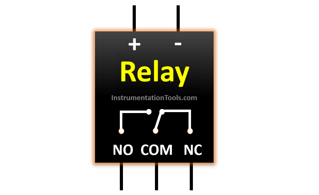
As discussed earlier, a relay has two types of contacts. Refer to the below image. Here, NO stands for normally open. This means that the wire connected to this contact will normally be open (or off) and the current will not flow when the relay is deactivated.

When the relay is activated by giving a power supply, the internal circuitry of the relay will be triggered which makes this contact closed (means the internal lever switch will be pushed to NO point) and current will now start flowing through this contact.

That is why, it is called normally open; because by default, this contact will not allow the flow of current unless energized.

Relay Parts

 What is an NC Contact?

In the above image, NC stands for normally closed. This means that the wire connected to this contact will normally be closed (or on) and current will flow when the relay is deactivated.

When the relay is activated by giving a power supply, the internal circuitry of the relay will be triggered which makes this contact open (means the internal lever switch will be pulled away from the NC point) and the current will now stop flowing through this contact.

That is why, it is called normally closed; because by default, this contact will allow flow of current unless energized.

This is the only difference between NO and NC contacts. NO contact is normally open and becomes closed once its coil is energized. NC contact is normally closed and becomes open once its coil is energized.

NO and NC contacts in PLC Programming

Let us have a look at how these two contacts are used in industrial automation programming. We will consider PLC for this and use ladder logic as a reference. See the below image.

NO and NC contacts in PLC programming

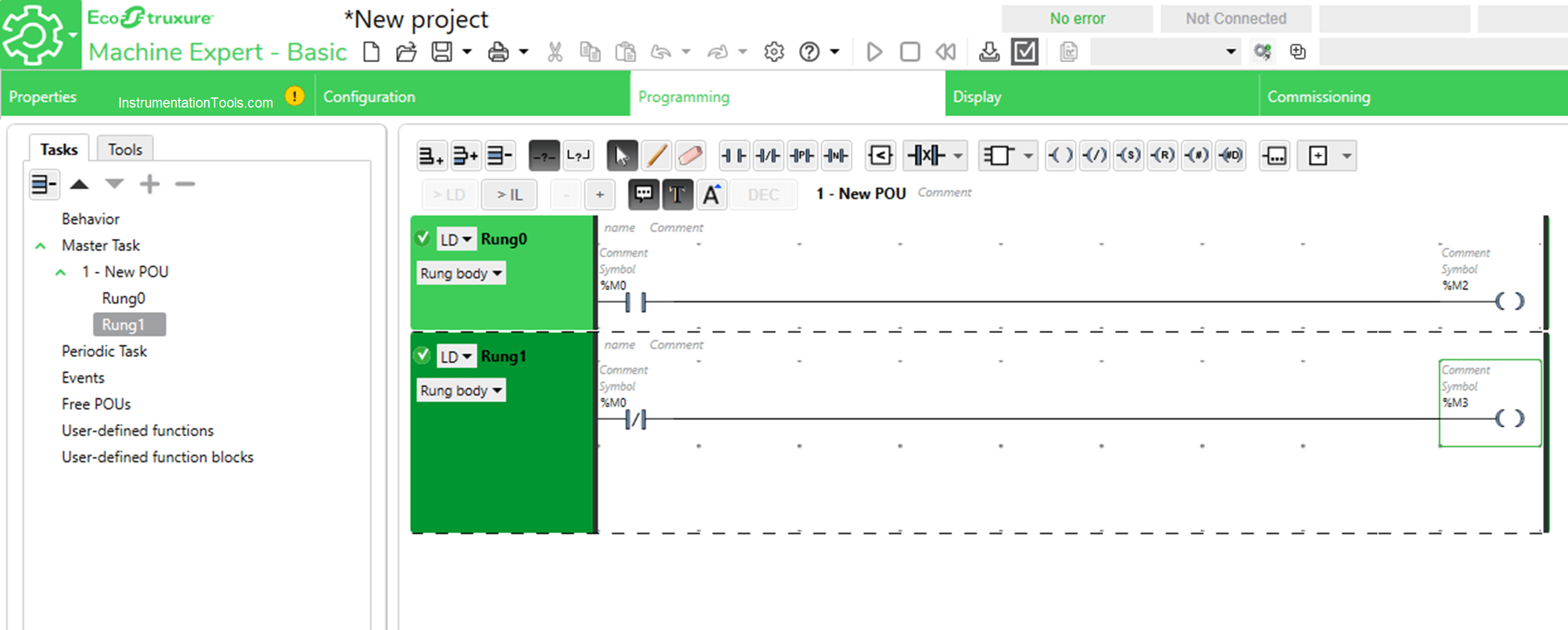
Referring to the above-discussed example, consider %M0 as a relay that has two contacts as shown in the above figure. The first rung uses its NO contact and the second rung uses its NC contact.

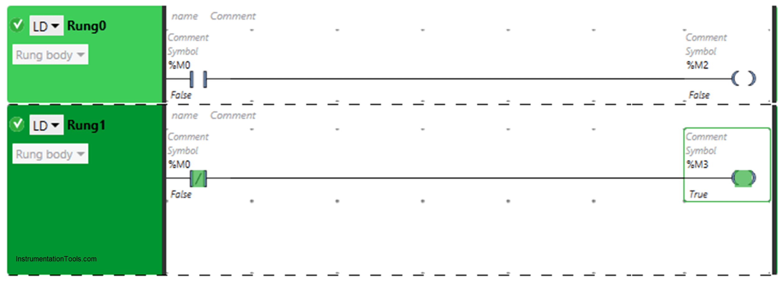
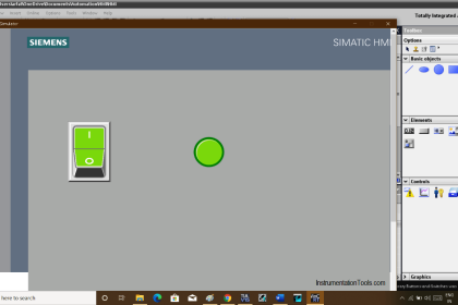
Now, refer to the below image. As the second rung uses NC contact, it will by default turn on %M3 coil; as the value of %M0 is zero (means the relay is off in electrical terms). At that time, %M2 will be off as the NO contact is also off.

Difference Between NO and NC Contacts

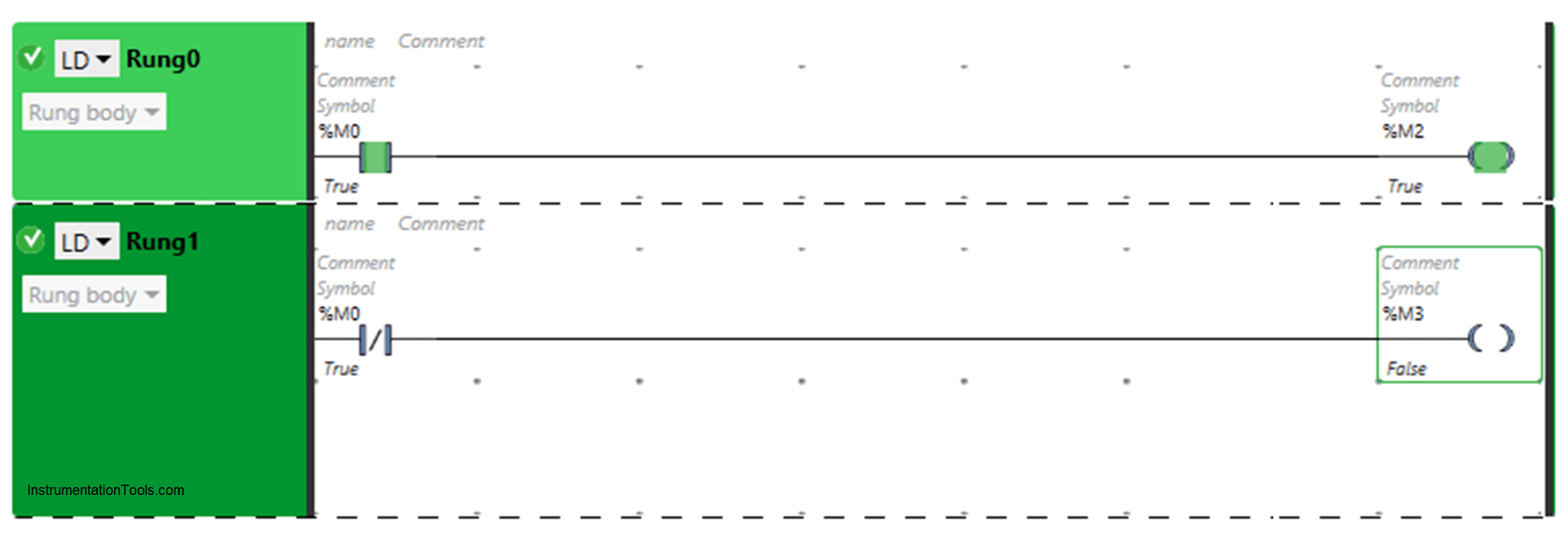
When the relay is energized, the NO contact used in first rung will turn on and power up %M2 coil as shown in below figure; as the value of %M0 is one (means the relay is on in electrical terms). At that time, %M3 will be off as the NC contact is also off.

What is an NO Contact

This helps clear the picture of NO and NC contacts. Basically, when one is working, the other will be off. It is as simple as that. The same concept is used to wire electrical circuits which use relay.

OpenPLC Programming - Difference between NO and NC Contacts

In this way, we understand the difference between NO and NC contacts.

If you liked this article, then please subscribe to our YouTube Channel for Electrical, Electronics, Instrumentation, PLC, and SCADA video tutorials.

You can also follow us on Facebook and Twitter to receive daily updates.

Read Next:

  • PLC Wiring Diagrams
  • Electrical Wiring Diagram
  • 4-20 mA Transmitter Wiring
  • Why 24 Volts DC Power Supply?
  • Interposing Relay Panel Wiring
Don't Miss Our Updates
Be the first to get exclusive content straight to your email.
We promise not to spam you. You can unsubscribe at any time.
Invalid email address
You've successfully subscribed !

Continue Reading

Control Speed of Induction Motor using Analog Output of PLC
PLC Program for Latching and unlatching Circuit
Emergency Stop Switch Spurious Trip
Compare Two Offline PLC Projects
How to Configure an Alarm in InTouch SCADA?
History of Programmable Logic Controllers (PLC)
Share This Article
Facebook Whatsapp Whatsapp LinkedIn Copy Link
Share
2 Comments
  • H.danesh says:
    January 22, 2023 at 4:21 pm

    Hello
    Please answer this question because it was not in your content. Do the close and open contacts of a relay select equal power to the load
    Thank you

    Reply
  • sachin says:
    July 3, 2025 at 10:36 pm

    very confusing article

    Reply

Leave a Reply Cancel reply

Your email address will not be published. Required fields are marked *

Stay Connected

128.3kFollowersLike
69.1kFollowersFollow
210kSubscribersSubscribe
38kFollowersFollow

Categories

Explore More

Motor Trip Logic using PLC Programming
PLC Sequence Programming Ladder Logic
How to Upload Siemens PLC Programs?
Animation of Electromagnetic Relay
PLC Code to Start & Stop Motor and Pump as per Logic
Top 100+ SCADA Questions
Procedure for Connecting Allen Bradley PLC and PC – RS Logix 500
Tools Required for PLC Programmer to Carry at Site

Keep Learning

PLC Program using Bitwise Instructions

Allen Bradley Bitwise Logical Operations

MCQ on PLC (Programmable Logic Controller)

MCQ on PLC (Programmable Logic Controller)

In this article, we will learn the difference between Machine Expert Basic and Machine Expert software in Schneider PLC.

Difference between Machine Expert Basic and Machine Expert – Schneider PLC

Scan cycle of a Siemens PLC

OB1 – Main Cyclic Organization Block in TIA Portal

Open Loop and Closed Loop System Questions

Open Loop and Closed Loop System Questions Answers

Logic for Always ON and Always OFF bit

Always ON and OFF Bit using Ladder Logic and Statement List

Set the S5 timer value by a memory word

Set the S5 Timer Value by a Memory Word

Ladder Rung with Two Outputs

PLC Multiple Outputs Configuration

Learn More

Bipolar Junction Transistors Questions & Answers

Measurement and Instrumentation Objective Questions – Part 1

L2F insertion-style flowmeter

Optical Flow Meter Principle

Erratic Radar Level Gauges

Erratic Radar Level Gauges Delays a Refinery Commissioning

Foundation Fieldbus Segment Topology

Foundation Fieldbus (FF) Segment Topology

valve packing assembly

What is Valve Packing ?

Power Systems Questions & Answers

Power Systems MCQ Series 3

Traces in TIA Portal

What is Trace Function in Tia Portal?

Commissioning Checklist for Industrial Automation System

Commissioning Checklists for Industrial Automation Systems

Menu

  • About
  • Privacy Policy
  • Copyright

Quick Links

  • Learn PLC
  • Helping Hand
  • Part Time Job

YouTube Subscribe

Follow US
All rights reserved. Reproduction in whole or in part without written permission is prohibited.
Welcome Back!

Sign in to your account

Username or Email Address
Password

Lost your password?