Inst ToolsInst ToolsInst Tools
  • Courses
  • Videos
  • Q & A
    • Interview
      • Instrumentation
      • Electronics
      • Electrical
      • Practical Questions
    • MCQ
      • Instrumentation MCQ
      • Electrical MCQ
      • Electronics MCQ
      • Control Systems MCQ
      • Analog Electronics MCQ
      • Digital Electronics MCQ
      • Power Electronics MCQ
      • Microprocessor MCQ
      • Multiple Choice Questions
  • EE
    • Electronics
      • Electronics Q & A
      • Electronic Basics
      • Electronic Devices & Circuits
      • Electronics Animation
      • Digital Electronics
    • Electrical
      • Electrical Basics
      • Electrical Q & A
      • Power Electronics
      • Electrical Machines
      • Electrical Animation
      • Power Systems
      • Switchgear & Protection
      • Transmission & Distribution
  • Measure
    • Control Valves
    • Calibration
    • Temperature
    • Pressure
    • Flow
    • Level
    • Analyzers
    • Switches
    • Vibration
    • Solenoid Valve
  • Control
    • PLC Tutorials
    • Control Systems
    • Safety Instrumented System (SIS)
    • Communication
    • Fire & Gas System
  • More
    • Design
    • Tools
    • Animation
    • Basics
    • Formulas
    • Standards
    • TextBooks
    • Common
    • Software
    • Excel Tools
    • Erection & Commissioning
    • Process Fundamentals
    • Videos
    • Books
Search
All rights reserved. Reproduction in whole or in part without written permission is prohibited.
Font ResizerAa
Inst ToolsInst Tools
Font ResizerAa
  • Courses
  • PLC Tutorials
  • Control Systems
Search
  • Courses
  • Videos
  • Q & A
    • Interview
    • MCQ
  • EE
    • Electronics
    • Electrical
  • Measure
    • Control Valves
    • Calibration
    • Temperature
    • Pressure
    • Flow
    • Level
    • Analyzers
    • Switches
    • Vibration
    • Solenoid Valve
  • Control
    • PLC Tutorials
    • Control Systems
    • Safety Instrumented System (SIS)
    • Communication
    • Fire & Gas System
  • More
    • Design
    • Tools
    • Animation
    • Basics
    • Formulas
    • Standards
    • TextBooks
    • Common
    • Software
    • Excel Tools
    • Erection & Commissioning
    • Process Fundamentals
    • Videos
    • Books
Follow US
All rights reserved. Reproduction in whole or in part without written permission is prohibited.
Inst Tools > Blog > Control Systems > Design Process Graphics in Factory Talk View Studio with an Analog Input

Design Process Graphics in Factory Talk View Studio with an Analog Input

In this article, you will learn the configuration of Analog input (P-AIn) Process Graphics in Factory Talk view Studio.

Last updated: July 23, 2022 12:07 am
Editorial Staff
Control Systems
No Comments
Share
4 Min Read
SHARE

In this article, you will learn the configuration of Analog input (P-AIn) Process Graphics in Factory Talk view Studio.

We are going to Configure Analog Input as a temperature transmitter in FT view Studio with PlantPAx DCS Library 4.10.00.

It Helps you to view Analog Input as a better functionality with user-based objects which helps you understand and troubleshoot the operation.

Factory Talk View Studio Process Graphics

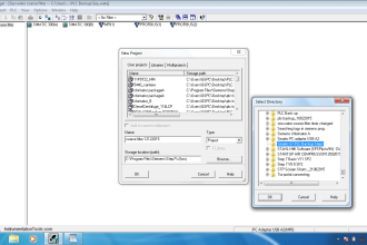
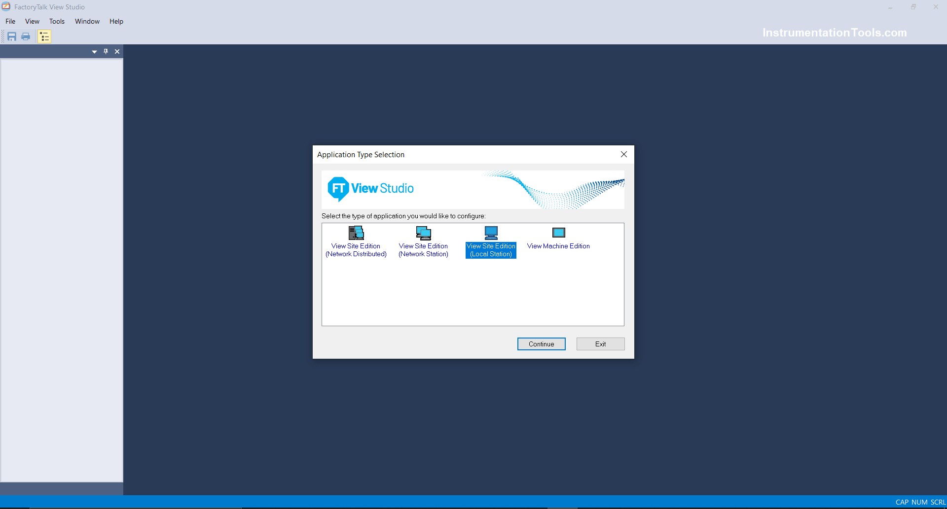
Step 1: Open Factory Talk View Studio SE Application as shown below and click on Local Station/Network Distributed as per system architecture.

Factory Talk View Studio SE Application

Step 2: After selecting the local station/Network Distributed click on a project created previously or create a new project.

PlantPAx New Project

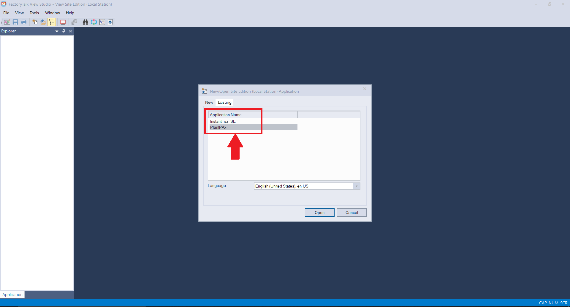
In the language section, select the language appropriately or else it can lead to errors in process graphics.

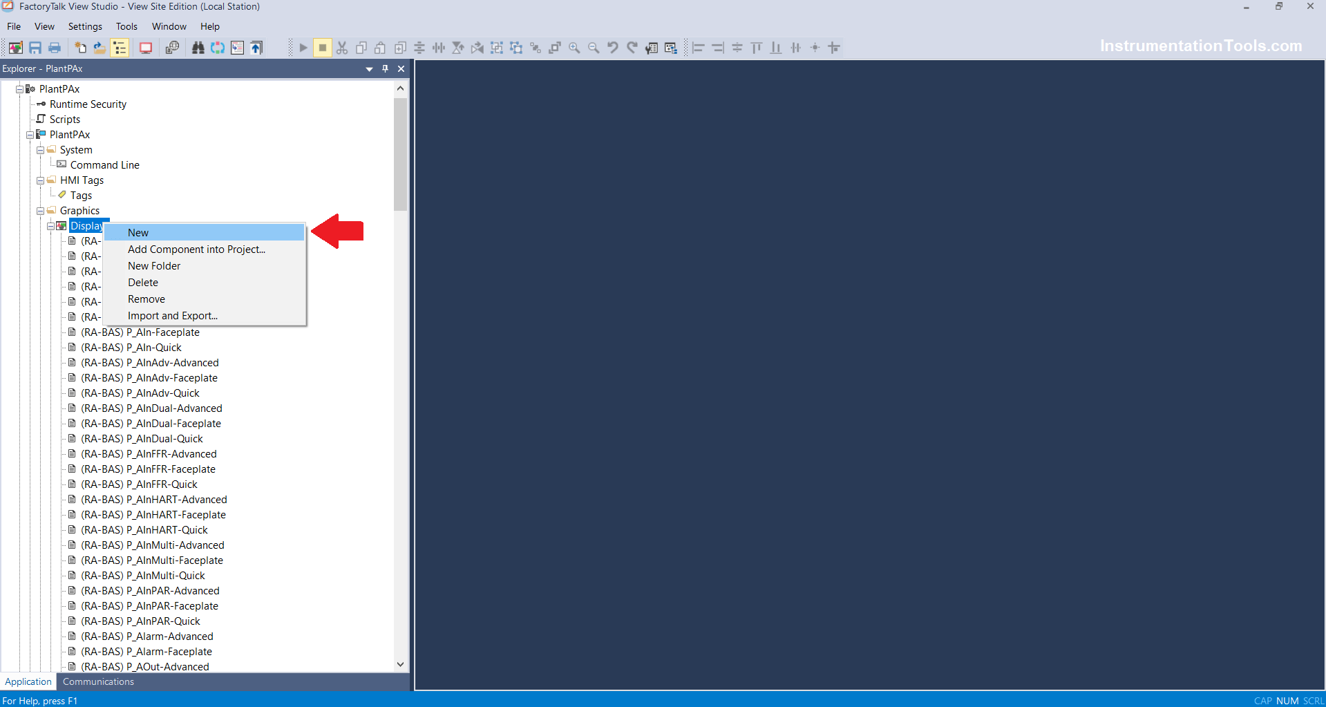
Step 3: After Opening the Project Right Click on Display and Click on New, to create a new display.

FactoryTalk View Studio Process Graphics

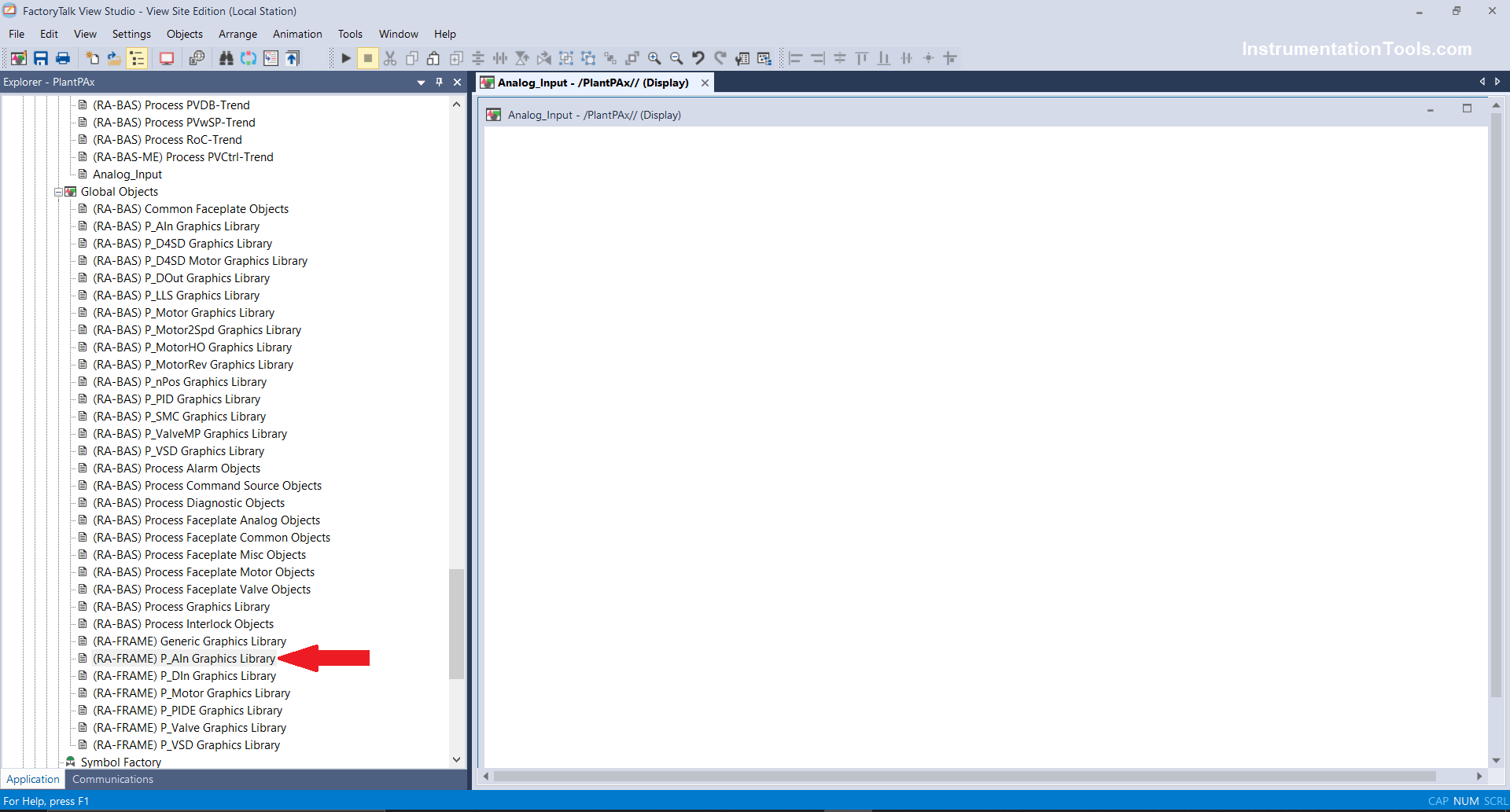
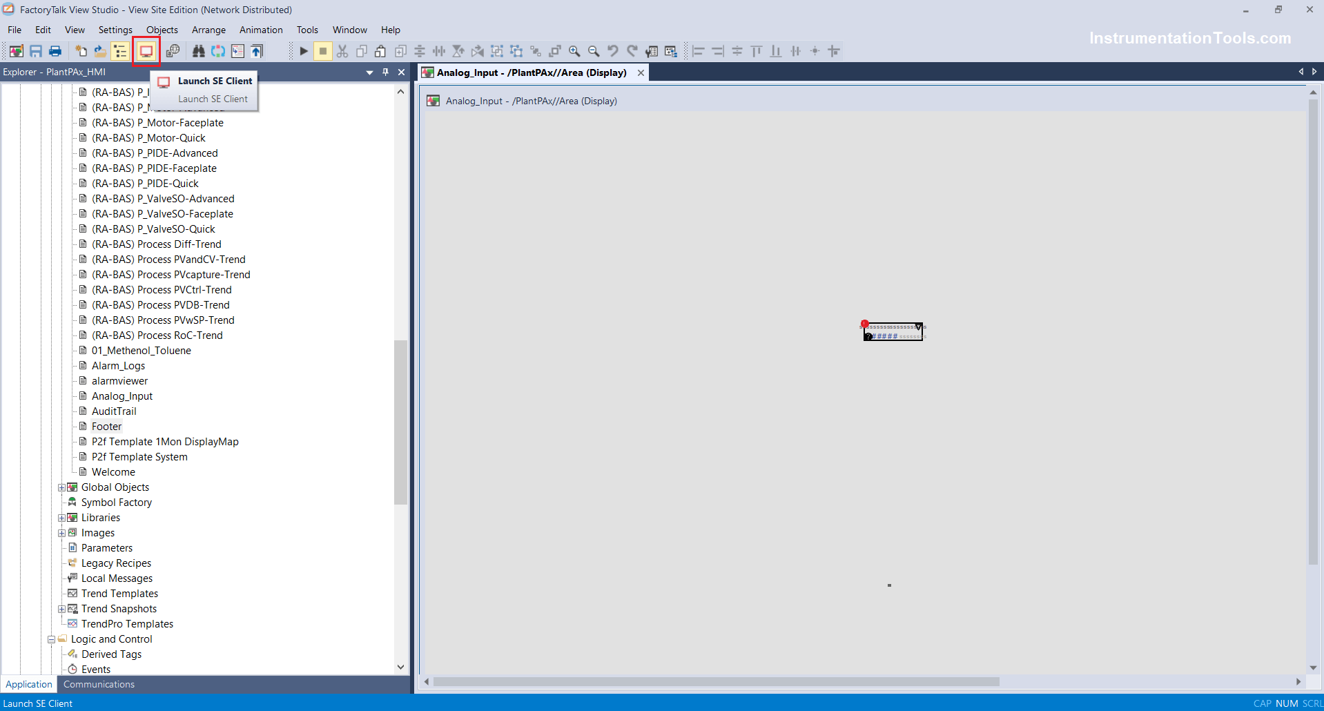
Step 4: After creating a new project (I have created an Analog-Input display) open the P-AIN Graphics Library from the global objects section.

P-AIN Graphics Library

Step 5: Analog inputs in the library are applicable for the Analog input block, Analog input advance block, etc.

Analog inputs in library

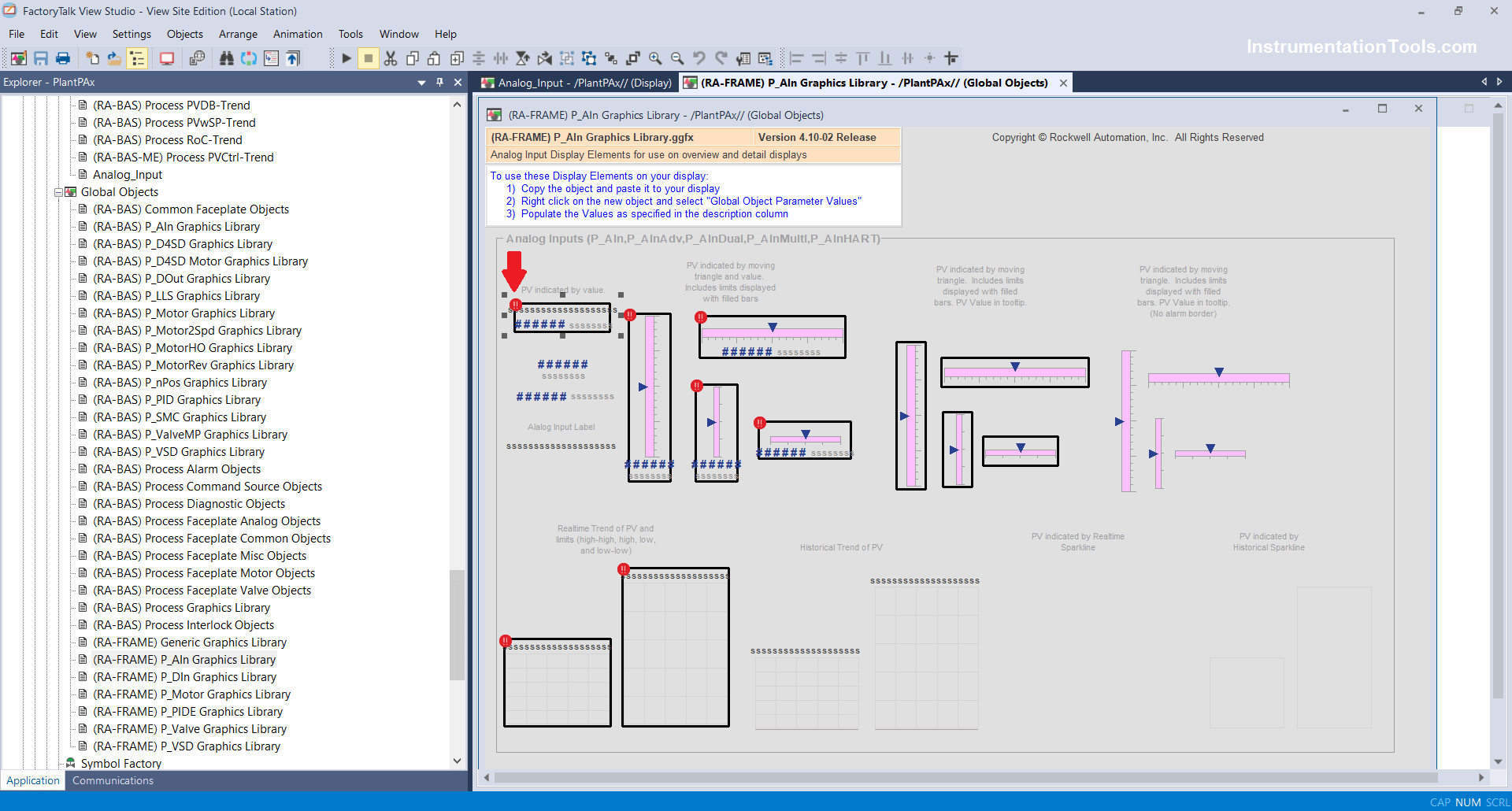
Select and copy PV Indicated by value Analog input from the library as shown below.

Since there are other analog input display bars also but which we are selecting are standard one which has all relevant objects needed for operation.

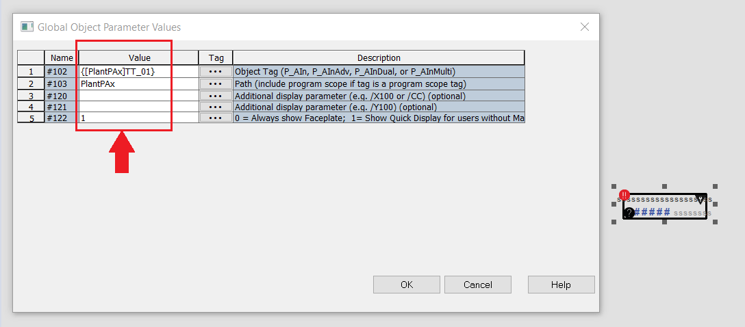
Step 6: Once copied in the display, right-click on the object and click on Global Object parameter values.

Global Object parameter values.

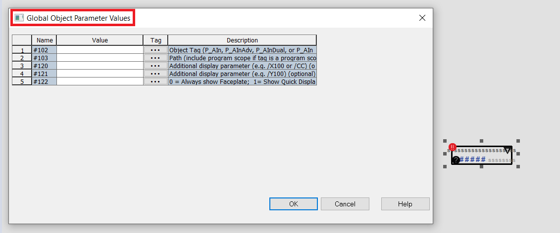
In#102: Enter Object Tag

In#103: Enter Path

In#120&#121: If an additional display parameter requires then you can enter X (*) or CC, which means it will help you to display the parameter popup as per your coordinates set in runtime (It is optional).

In#122: Enter as value 1 and click on OK.

FactoryTalk View display parameter

Step 7: Same you can configure for required analog inputs such as Flow Transmitter, Pressure Transmitter, Weight Transmitters, etc.

Step 8: Click on the Runtime button to launch runtime.

FactoryTalk View Studio Runtime button

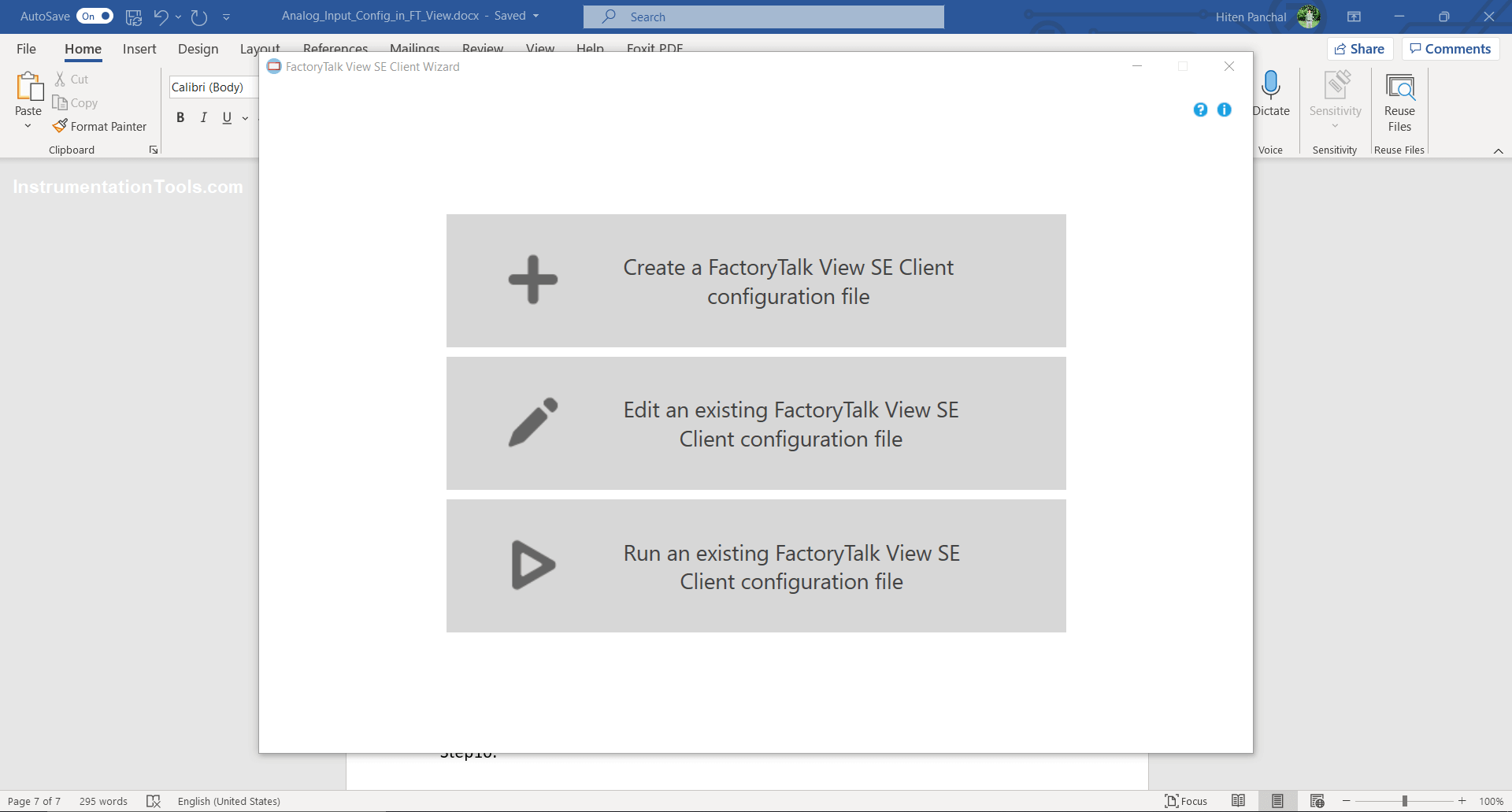
Step 9: Click on create SE runtime (Client file)

FactoryTalk View SE Client View

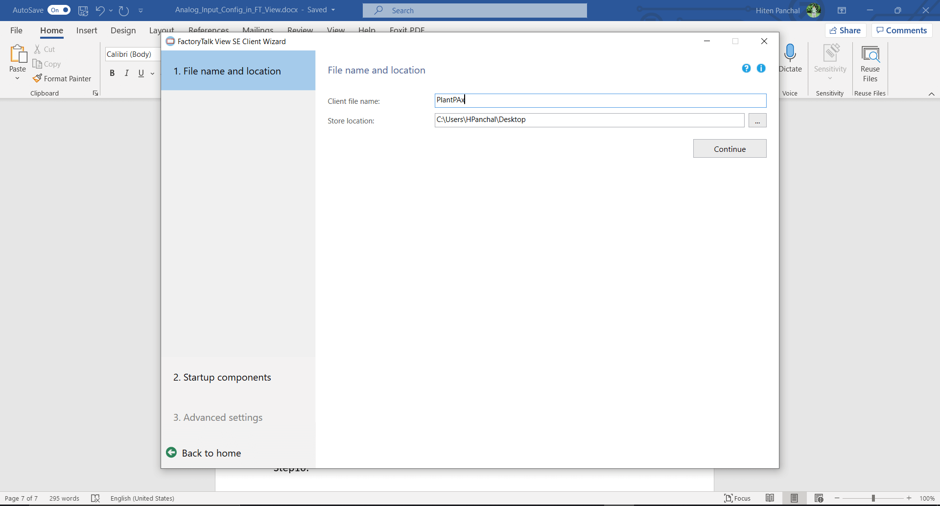
Step 10: write the file name as you want, I have written it as PlantPAx, and click on continue.

FactoryTalk Vie Studio File

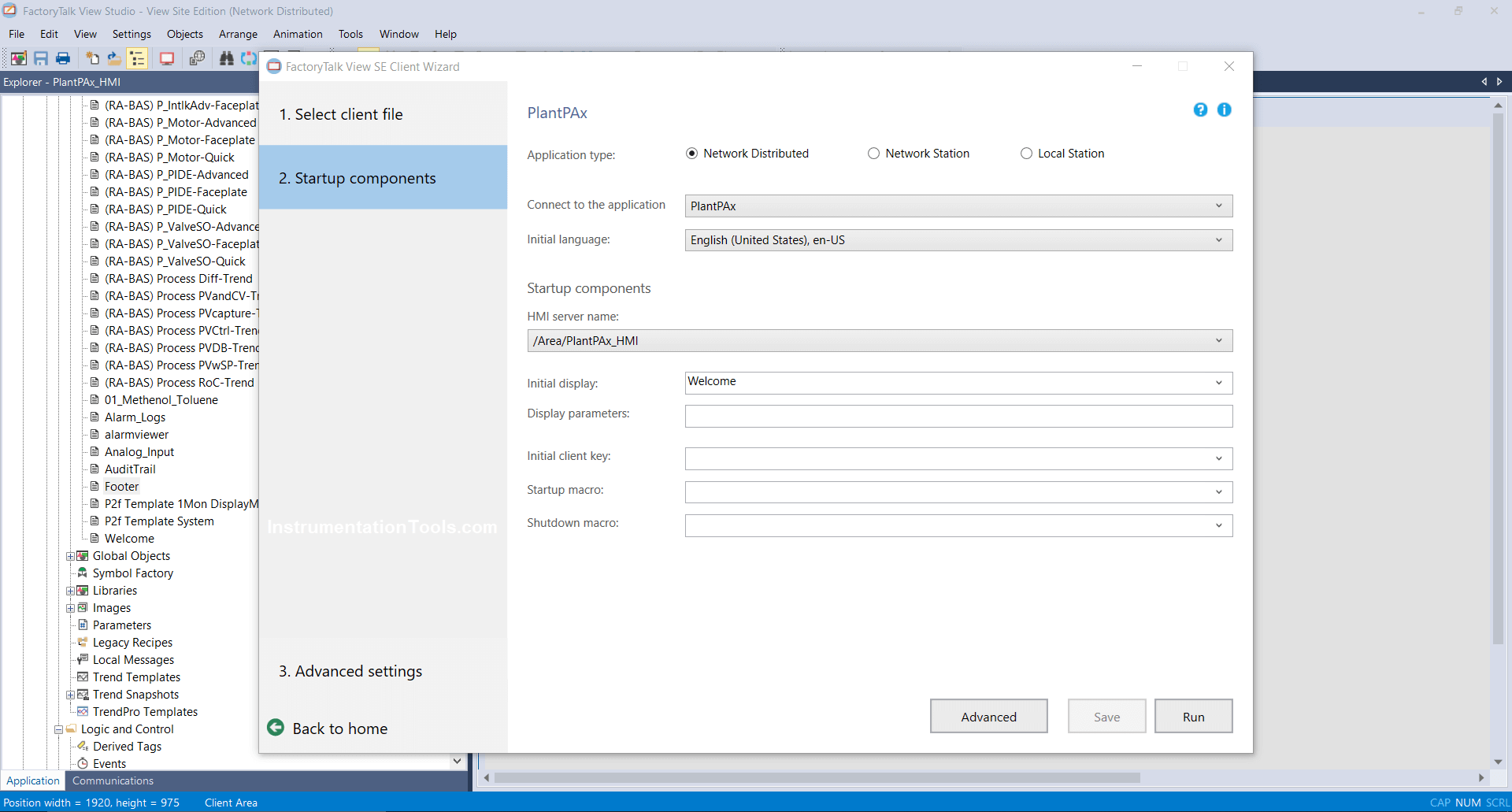
Step 11: Select application type if it is a network distributed, then need to select HMI Server name and Initial Display name, if required you can select macros or else leave blank.

PlantPAx File

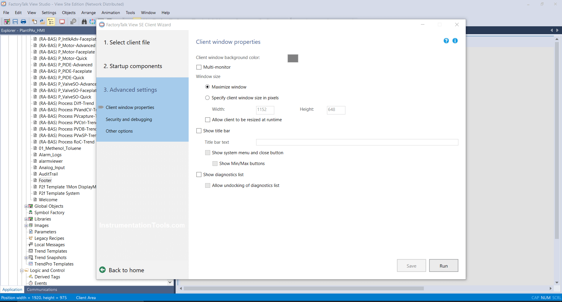
Step 12: Click on the Advanced button deselect all and select maximize the window and click on save and run.

FactoryView Talk Studio Client Window

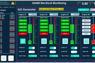
Step 13: After clicking on run you will see Runtime Screen with Analog input as shown below.

Runtime Screen with Analog input

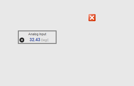
Step 14: Click on Analog Input to view Faceplate as shown below.

Analog Input to view Faceplate

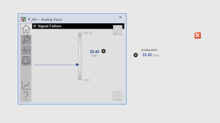
Home Button shows Analog-Input value in units with trends as shown below image.

FactoryTalk View Studio trends

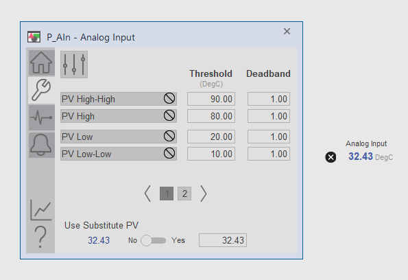
The settings button indicates your threshold and dead band values you can configure
here as well as in logic.

Raw Input in PlantPAx

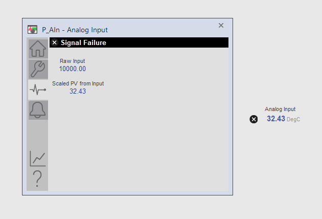
This button indicates Raw input and Process value from raw input through scaling.
Note: Signal failure is showing because I have not connected any IO modules.

Process value in FactoryTalk View Studio

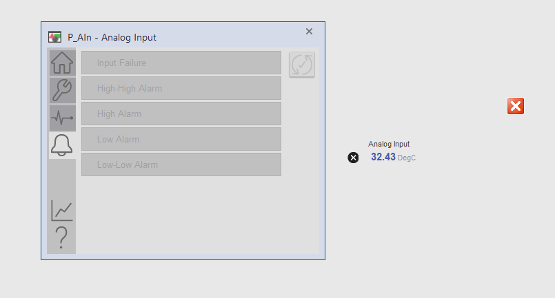
The alarm Button shows HI, HIHI, LO, and LOLO alarms tab, they will flash when the analog input value reaches beyond defined limits.

real time data in PlantPAx

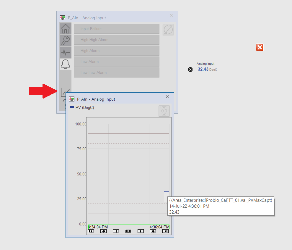
Trend Button shows Actual real-time data or value of transmitter you can view logged value for a specific time.

Don't Miss Our Updates
Be the first to get exclusive content straight to your email.
We promise not to spam you. You can unsubscribe at any time.
Invalid email address
You've successfully subscribed !

Continue Reading

Difference Between Serial and Parallel Communication
What is a Transducer ?
Relay Operation, Types, Symbols & Characteristics
DCS Quiz
Heuristic PID Tuning Procedure
Comparison of Control Loops – Open, Closed, Cascade, Feedforward, Ratio
Share This Article
Facebook Copy Link Print
Share
Leave a Comment

Leave a Reply Cancel reply

Your email address will not be published. Required fields are marked *

Stay Connected

128.3kFollowersLike
69.1kFollowersFollow
208kSubscribersSubscribe
38kFollowersFollow

Categories

Explore More

Transmitters 4-20mA Current Failure Alarm Limits
Basics of Process Control Systems
How Engineers Effectively do Problem-solve and Troubleshoot?
How is Data Stored in Standard Modbus Protocol?
Recognizing a Porpoising PID Controller
4-wire Transmitters Current Loops
Basic Concepts of the Safety Relay
Animation of Electromagnetic Relay
Open Loop and Closed Loop System Questions Answers
Design and Implement Motor Control – Electrical Engineering

Keep Learning

Design Process Control & Safety Systems

Design View of Supplying Process Control and Safety Systems

On-Off Controller example

ON-OFF Controller Principle

Industrial Automation Mobile Apps

Industrial Automation Mobile Apps

Tips for Reducing the Noise Signals

Tips for Reducing the Noise Signals

Split range control scheme

Overview of Split Range Control

Control Valve Direction of Control Action

PID Controller Action : Directing Acting & Reverse Acting

PID Simulator

PID Simulator Download

Difference Between PNP and NPN Sensors

Difference Between PNP and NPN Sensors

Discover More

Two Tanks Filling using PLC

PLC Ladder Logic for Tanks Filling as per Priority

two-way communication between PLC systems

Transferring Data Across PLC Systems – TSEND_C and TRCV_C

Electrical Machines Questions and Answers

Induction Motor Rotor Frequency

parallel-resistors-circuit-example

Series and Parallel Resistors

Interferometer Principle

Interferometer Principle

Piston Flow Meters Working Animation

Piston Flow Meters Working Principle with Animation

Pressure based Flowmeters

Pressure based Flow Meters

Sensor Based Projects List - Electronics & Electrical

350+ Sensor-Based Projects List – Electronics & Electrical

Follow US
All rights reserved. Reproduction in whole or in part without written permission is prohibited.
Welcome Back!

Sign in to your account

Username or Email Address
Password

Lost your password?