PlantPAx Library consists of a set of Add-on-blocks for configuring parameters and operating analog inputs, analog outputs, digital inputs, and digital outputs.
Import Add-On Instructions in Studio 5000
We will Import all required add-on-instructions to help us create instructions for analog inputs, analog outputs, digital inputs, and digital outputs.
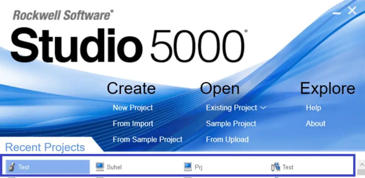
Step1: Open Studio 5000. Click on New Project and Select controller.
If you have PLC Hardware you can choose Specific Controller from the list and type the name of the project you want and click on Next.
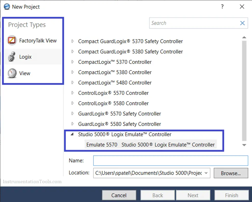
I have selected Emulator (Studio 5000 Logix emulate)
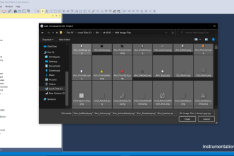
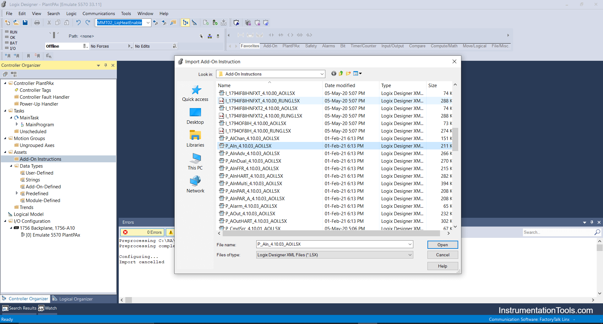
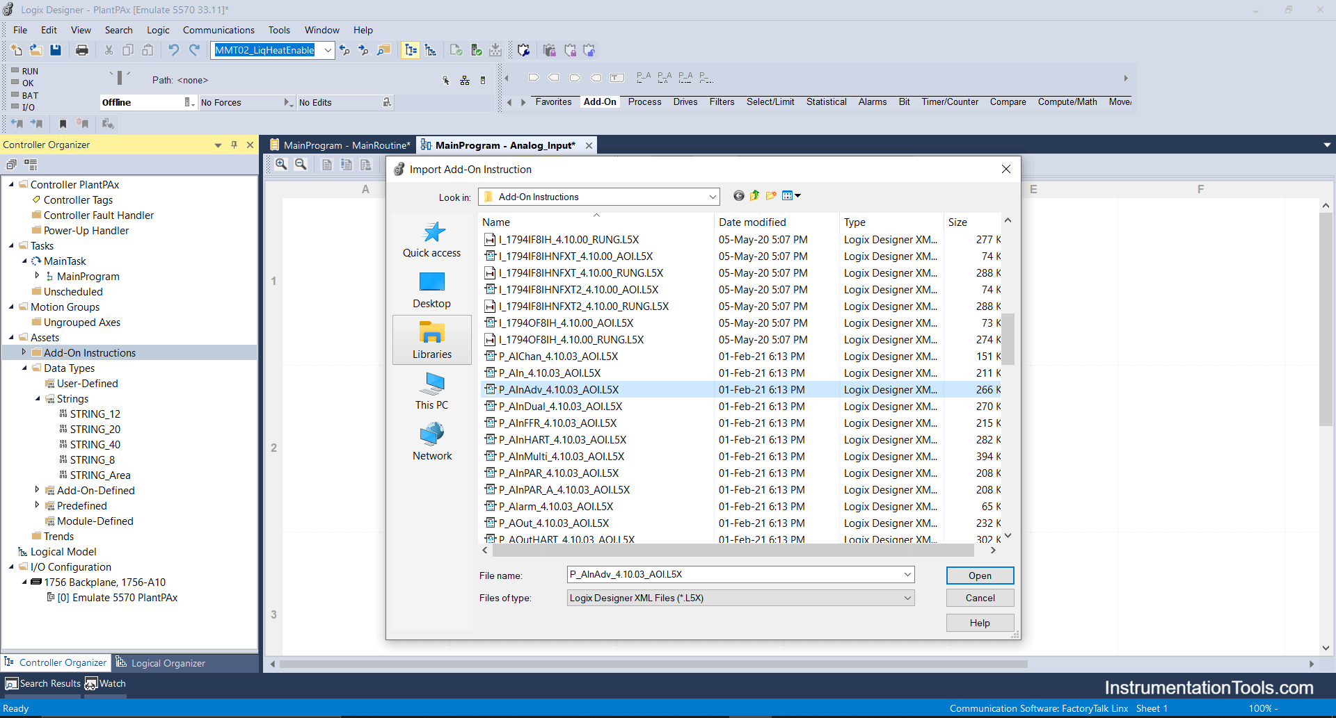
Step 2: Right Click on Add on Instructions and click on Import add on Instructions.
For Analog Inputs, Select all P-AIN Add-On-Instructions as per requirements as shown below.
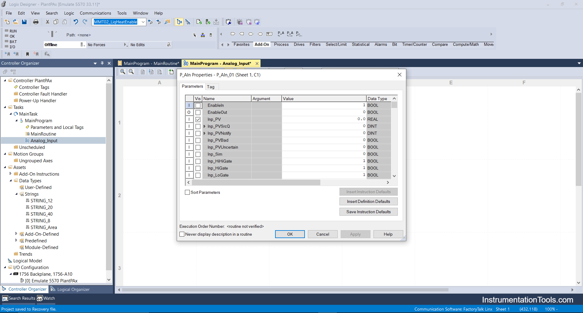
P-AIN- It states Analog Input block as shown below.
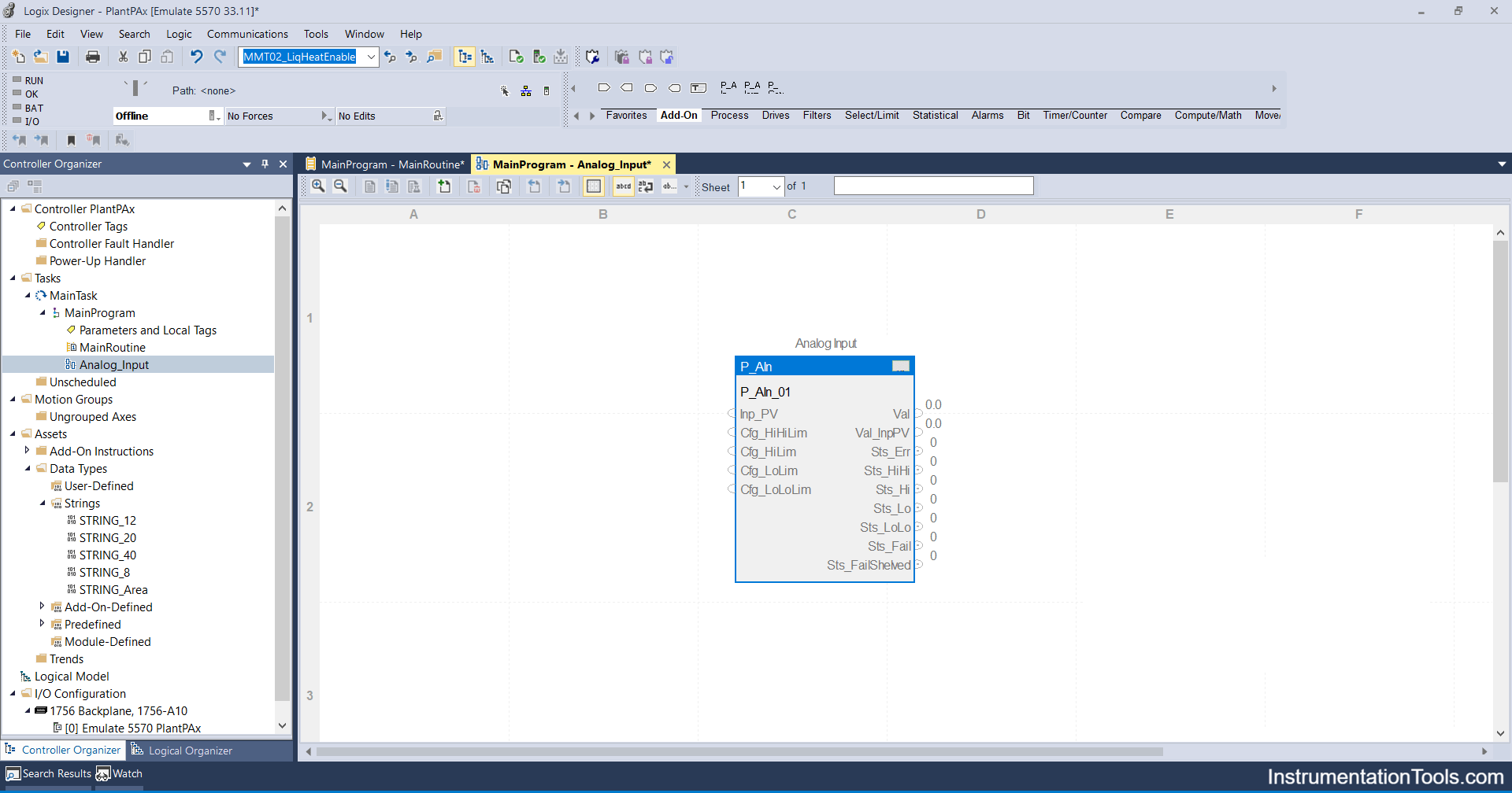
Below are the Parameters, according to requirements you can choose.
Step 3: Import all required analog input add-on instructions similarly.
Please note below add-on-instruction will work on the Functional block diagram routine only as it indicates the FBD symbol.

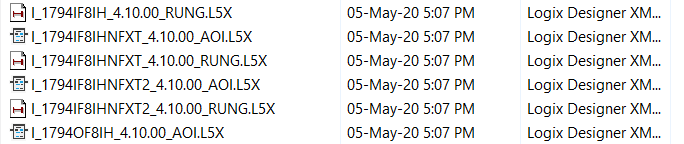
You will see some add-on instructions in the list that will work on the Ladder diagram only.
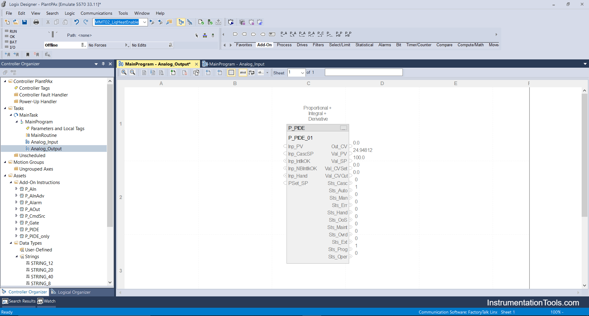
Step 4: For analog outputs, for the control valve, I will be using the P_PIDE add-on block as it has better functionality for tuning and better scalable parameters.
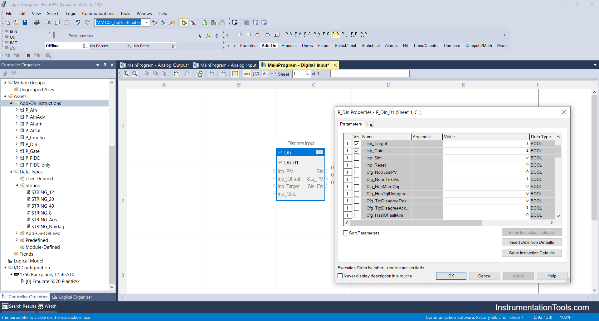
Step 5: Now I will import the Digital input add-on block eg: it can be used for limit switches, relays, etc. as per your availability and requirements of parameters you can select the checkboxes.
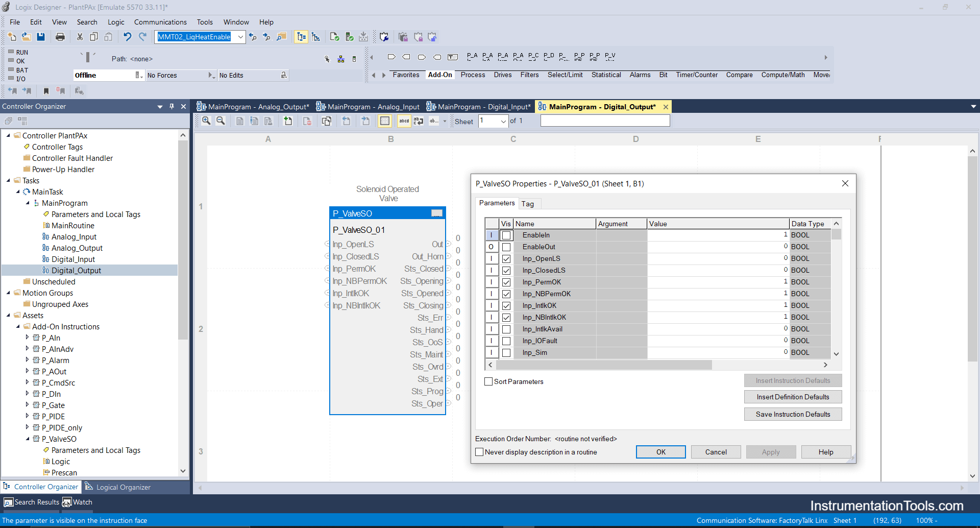
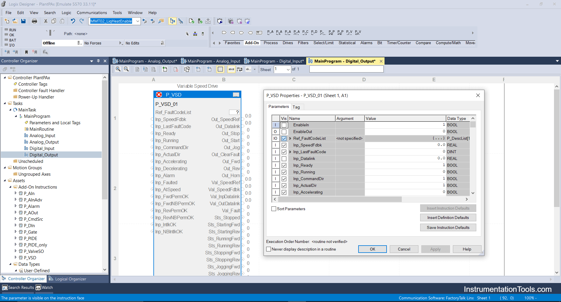
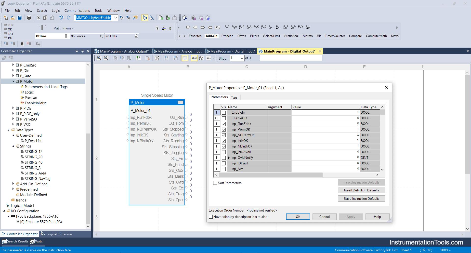
Step 6: Next I will import Digital _Output add-on instructions, this can be used for configuring and operating On-Off valves, dampers, electrical motors, indicators and alarm bells.
a. Digital Output block add-on for Solenoid On-Off valve.
b. Digital output block add-on for Variable speed drive.
c. Digital Output block for Motor
Step 7: Now I will be importing the most important and frequently used add-on block called “Interlock” which can be used anywhere to provide interlock to any device for the legitimate process.
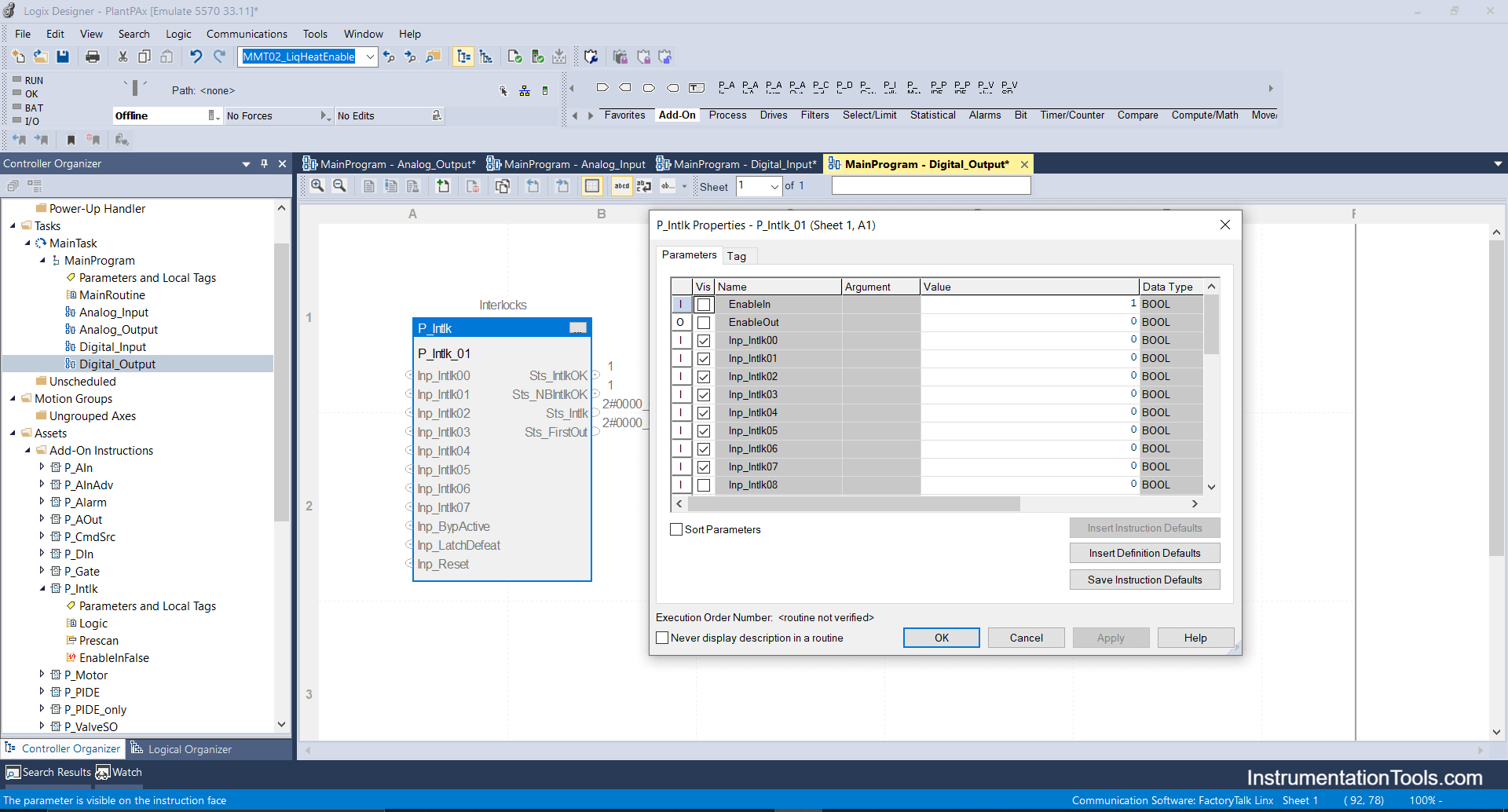
Interlock block has a 16-bit array i.e you can configure 16 interlocks for a valve or motor or any digital output devices.
If you liked this article, then please subscribe to our YouTube Channel for Electrical, Electronics, Instrumentation, PLC, and SCADA video tutorials.
You can also follow us on Facebook and Twitter to receive daily updates.
Read Next:
- Import PlantPAx Library
- DCS Technical Evaluation
- Download PlantPAx Library
- Condensing Turbine System
- Cloud PLC and SCADA System