Another common electrical pressure sensor design works on the principle of differential capacitance. In this design, the sensing element is a taut metal diaphragm located equidistant between two stationary metal surfaces, comprising three plates for a complementary pair of capacitors. An electrically insulating fill fluid (usually a liquid silicone compound) transfers motion from the isolating diaphragms to the sensing diaphragm, and also doubles as an effective dielectric for the two capacitors:
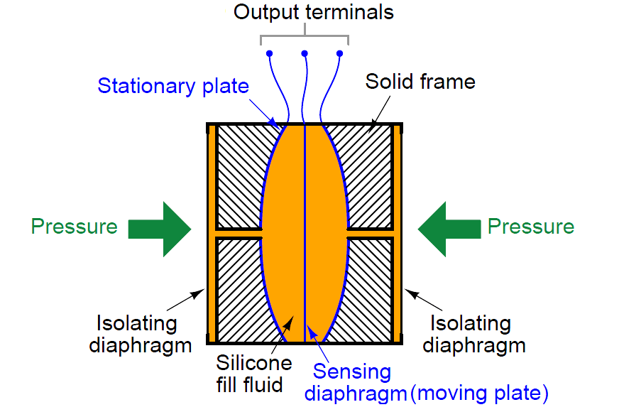
Any difference of pressure across the cell causes the diaphragm to flex in the direction of least pressure. The sensing diaphragm is a precision-manufactured spring element, meaning that its displacement is a predictable function of applied force. The applied force in this case can only be a function of differential pressure acting against the surface area of the diaphragm in accordance with the standard force-pressure-area equation F = PA.
In this case, we have two forces caused by two fluid pressures working against each other, so our force-pressure-area equation may be rewritten to describe resultant force as a function of differential pressure (P1 − P2) and diaphragm area: F = (P1 − P2)A. Since diaphragm area is constant, and force is predictably related to diaphragm displacement, all we need now in order to infer differential pressure is to accurately measure displacement of the diaphragm.
The diaphragm’s secondary function as one plate of two capacitors provides a convenient method for measuring displacement. Since capacitance between conductors is inversely proportional to the distance separating them, capacitance on the low-pressure side will increase while capacitance on the high-pressure side will decrease:
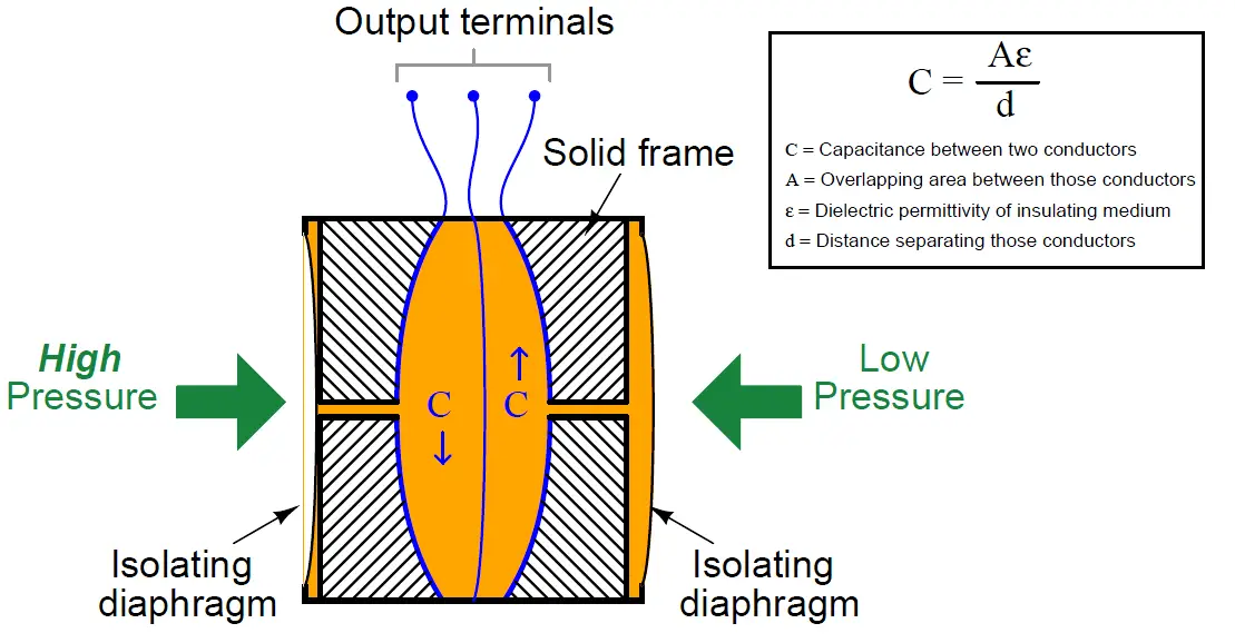
A capacitance detector circuit connected to this cell uses a high-frequency AC excitation signal to measure the different in capacitance between the two halves, translating that into a DC signal which ultimately becomes the signal output by the instrument representing pressure.
These pressure sensors are highly accurate, stable, and rugged. An interesting feature of this design – using two isolating diaphragms to transfer process fluid pressure to a single sensing diaphragm through an internal “fill fluid” – is that the solid frame bounds the motion of the two isolating diaphragms such that neither one is able to force the sensing diaphragm past its elastic limit.
As the illustration shows, the higher-pressure isolating diaphragm gets pushed toward the metal frame, transferring its motion to the sensing diaphragm via the fill fluid. If too much pressure is applied to that side, the isolating diaphragm will merely “flatten” against the solid frame of the capsule and stop moving. This positively limits the isolating diaphragm’s motion so that it cannot possibly exert any more force on the sensing diaphragm, even if additional process fluid pressure is applied. This use of isolating diaphragms and fill fluid to transfer motion to the sensing diaphragm, employed in other styles of differential pressure sensor as well, gives modern differential pressure instruments excellent resistance to over-pressure damage.
It should be noted that the use of a liquid fill fluid is key to this overpressure-resistant design. In order for the sensing diaphragm to accurately translate applied pressure into a proportional capacitance, it must not contact the conductive metal frame surrounding it. In order for any diaphragm to be protected against overpressure, however, it must contact a solid backstop to limit further travel. Thus, the need for non-contact (capacitance) and for contact (overpressure protection) are mutually exclusive, making it nearly impossible to perform both functions with a single sensing diaphragm. Using fill fluid to transfer pressure from isolating diaphragms to the sensing diaphragm allows us to separate the function of capacitive measurement (sensing diaphragm) from the function of overpressure protection (isolation diaphragms) so that each diaphragm may be optimized for a separate purpose.
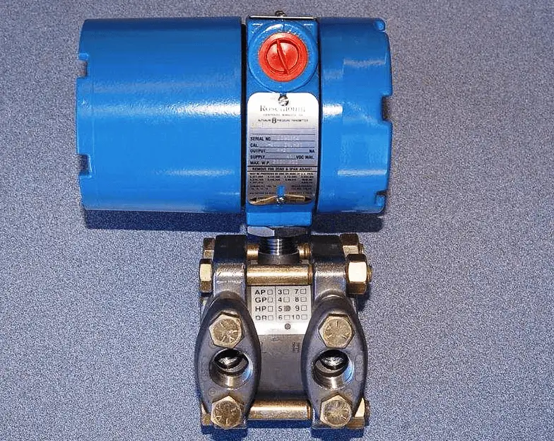
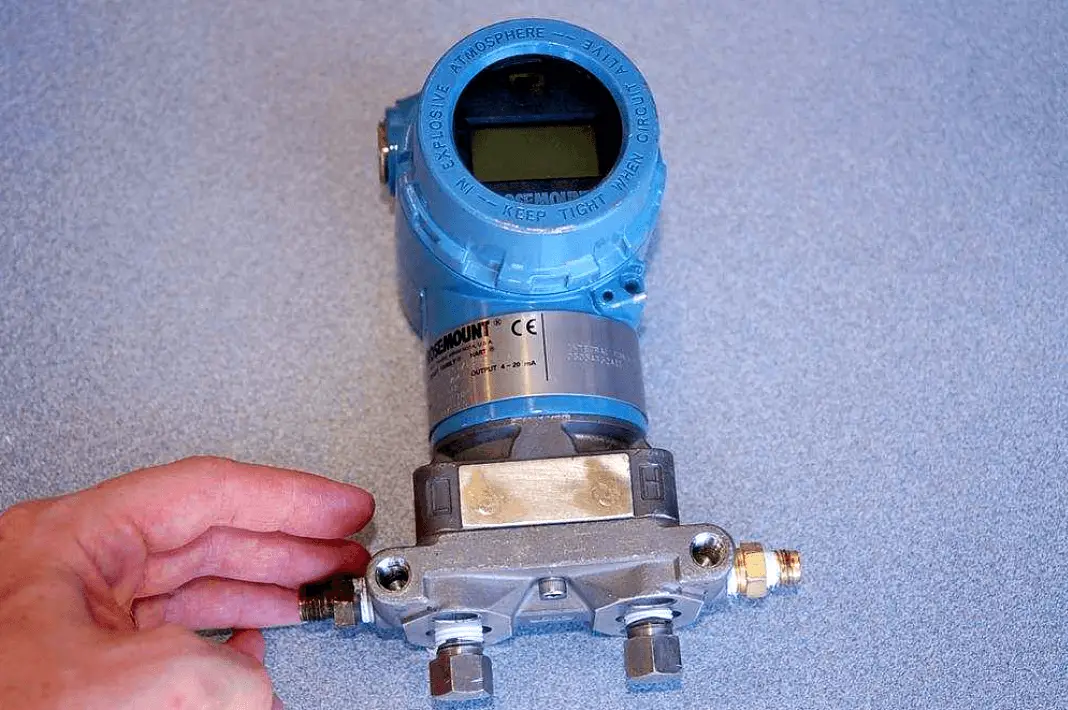
A classic example of a pressure instrument based on the differential capacitance sensor is the Rosemount model 1151 differential pressure transmitter, shown in assembled form in the following photograph:
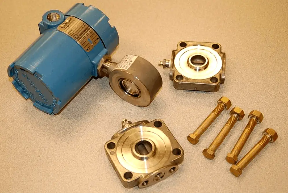
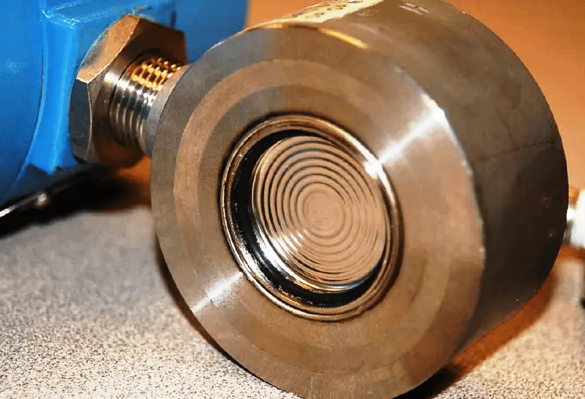
By removing four bolts from the transmitter, we are able to remove two flanges from the pressure capsule, exposing the isolating diaphragms to plain view:
A close-up photograph shows the construction of one of the isolating diaphragms, which unlike the sensing diaphragm is designed to be very flexible. The concentric corrugations in the metal of the diaphragm allow it to easily flex with applied pressure, transmitting process fluid pressure through the silicone fill fluid to the taut sensing diaphragm inside the differential capacitance cell:
The interior of the same differential capacitance sensor (revealed by cutting a Rosemount model 1151 sensor in half with a chop saw) shows the isolating diaphragms, the sensing diaphragm, and the ports connecting them together:
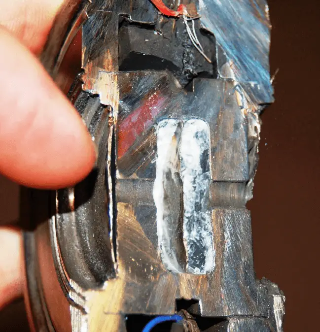
Here, the left-side isolating diaphragm is clearer to see than the right-side isolating diaphragm. A feature clearly evident in this photograph is the small clearance between the left-side isolating diaphragm and the internal metal frame, versus the spacious chamber in which the sensing diaphragm resides.
Recall that these internal spaces are normally occupied by fill fluid, the purpose of which is to transfer pressure from the isolating diaphragms to the sensing diaphragm. As mentioned before, the solid metal frame limits the travel of each isolating diaphragm in such a way that the higher pressure isolating diaphragm “bottoms out” on the metal frame before the sensing diaphragm can be pushed past its elastic limit. In this way, the sensing diaphragm is protected against damage from overpressure because the isolating diaphragms are simply not allowed to move any farther.
The differential capacitance sensor inherently measures differences in pressure applied between its two sides. In keeping with this functionality, this pressure instrument has two threaded ports into which fluid pressure may be applied. A later section in this chapter will elaborate on the utility of differential pressure transmitters. All the electronic circuitry necessary for converting the sensor’s differential capacitance into an electronic signal representing pressure is housed in the blue-colored structure above the capsule and flanges. A more modern realization of the differential capacitance pressure-sensing principle is the Rosemount model 3051 differential pressure transmitter:
As is the case with all differential pressure devices, this instrument has two ports through which fluid pressure may be applied to the sensor. The sensor, in turn, responds only to the difference in pressure between the ports.
The differential capacitance sensor construction is more complex in this particular pressure instrument, with the plane of the sensing diaphragm perpendicular to the plane of the two isolating diaphragms. This “coplanar” design is more compact than the older style of sensor, and more importantly it isolates the sensing diaphragm from flange bolt stress.
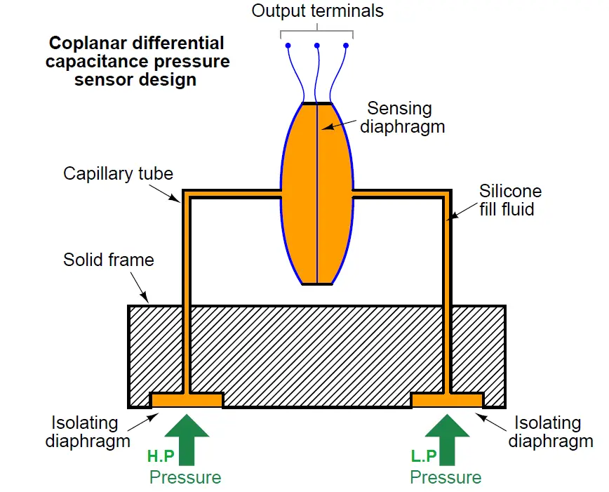
Take particular note of how the sensor assembly is not embedded in the solid metal frame as was the case with the original Rosemount design. Instead, the sensor assembly is relatively isolated from the frame, connected only by two capillary tubes joining it to the isolating diaphragms. This way, stresses inside the metal frame imparted by flange bolts have virtually no effect on the sensor.
A cutaway model of a Rosemount model 3051S (“supermodule”) DP transmitter shows how this all looks in real life:
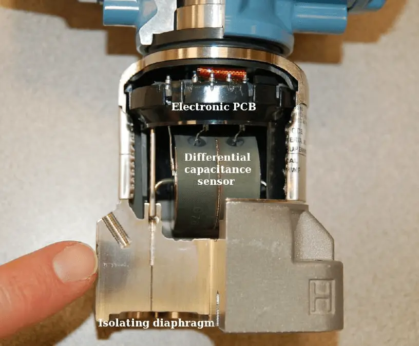
Process fluid pressure applied to the isolating diaphragm(s) transfers to fill fluid inside the capillary tubes, conveying pressure to the taut diaphragm inside the differential capacitance sensor. Like the classic Rosemount model 1151 design, we see the fill fluid performing multiple functions:
- The fill fluid protects the delicate sensing diaphragm from contact with unclean or corrosive process fluids
- The fill fluid allows the isolating diaphragms to provide overpressure protection for the sensing diaphragm
- The fill fluid provides a medium of constant permittivity for the differential capacitance circuit to function
The “supermodule” series of Rosemount pressure transmitters shares the same coplanar design as the earlier 3051 models, but adds a new design feature: inclusion of the electronics within the stainless-steel module rather than the blue-painted upper housing. This feature allows the transmitter size to be significantly reduced if needed for applications with limited space.
Credits : Tony R. Kuphaldt – Creative Commons Attribution 4.0 License


Nice notes.