In this article, you will learn about the deaerator pressure and level control system in power plants.
Contents
Some General Control Loop Information
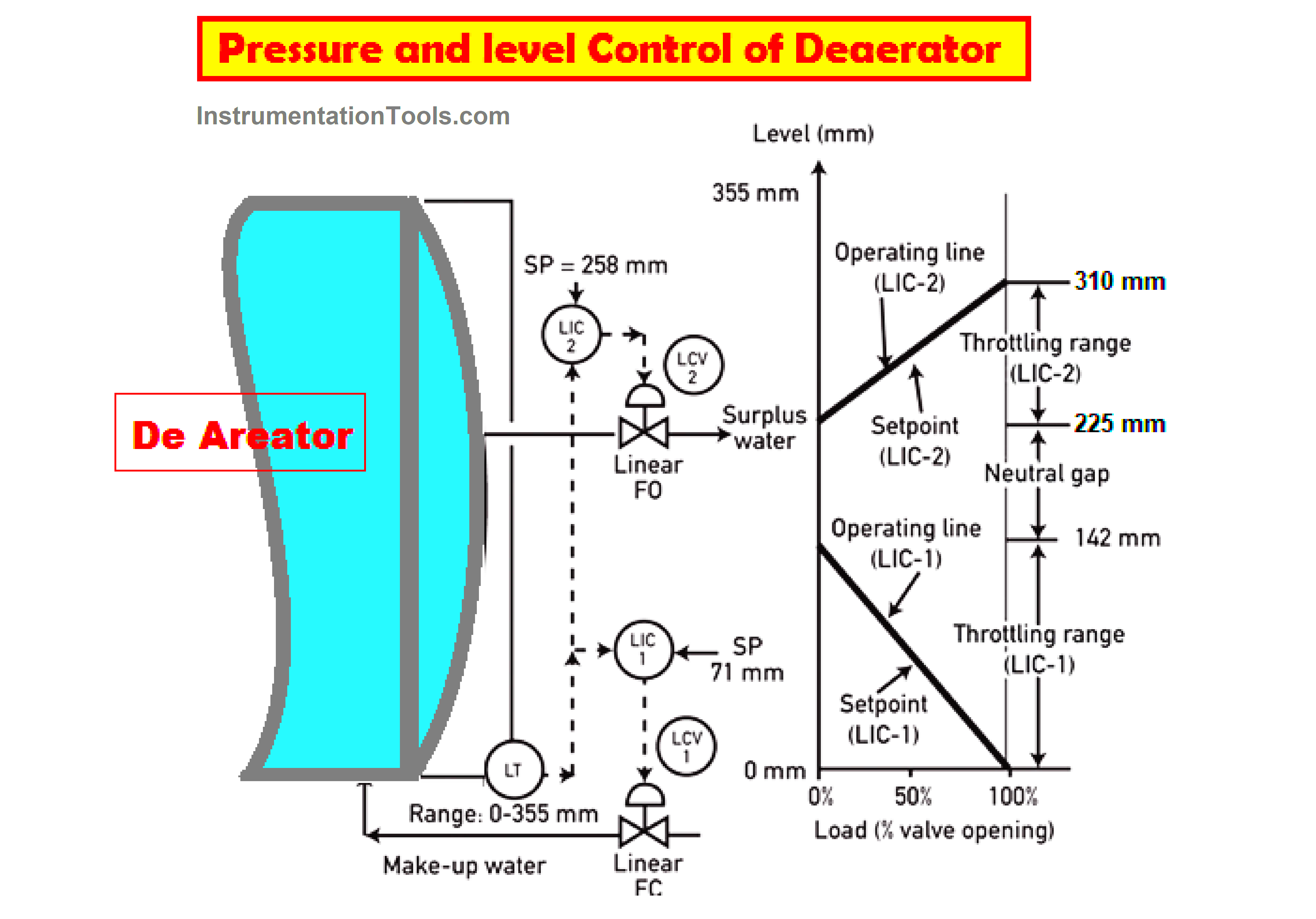
- The Make-Up control loop and valve and the other one is Surplus control loop and valve are two Deaerator level control loops.
- The set point valve of both makeup and surplus control loops are set to 150 mm and 225 mm, respectively.
- The actual level of the Deaerator is set to a range of 0 mm to 355 mm.
- Make-up water is indirectly supplied to the de-aerator i.e. the feed water initially flows through the condenser and condenser level loop and the surplus goes back to the condenser.
- According to the loop design, the relation between level control error and the valve’s position must be linear.
- For the level error range of 0 mm to 150 mm the position of the corresponding makeup valve must lie between 0% to 100%.
- But the controlling action must initialize only when the deaerator level falls below 150 mm.
- The makeup water valve must get opened fully when the level reaches 0 mm.
- The surplus valve position must lie between 0% to 100% to maintain a range of 225 mm to 310 mm.
- Here in this case the controlling action must initialize only when the deaerator level rises above 225 mm.
- The surplus valve must get opened fully when the level reaches 310 mm.
- Note that both make-up control loop valves and surplus control loop valves must be in a closed position when the level lies between 150 mm and 225 mm.
- Due to the above requirements, both these makeup and surplus control loops are implemented in Distributed Control Systems DCS using Proportional (P) Controllers.
- The gain for the makeup control loop is – 2.5 and for the surplus control loop is + 4.17
| Make-Up Level Controller LIC I | Sur-Plus Level Controller LIC II | |
| Set Point | 71 mm | 258 mm |
| Throttling Range | 142 mm | 310-225= 85 mm |
| Controller action | Reverse | Direct |
| Controller gain | 355/142 = – 2.5 | 355/85 = + 4.17 |
| Valve characteristics | Linear | Linear |
| Valve Failure Position | Open | Close |
Deaerator Level Control
In this level control technique
- For each unit, the two condensers are provided to operate in parallel but the same hot well level must be maintained at both the condensers.
- Interlock actions must be ruled by the signals generated from control instrumentation provided on these condensers.
- In low level three level switches LSW-401, LSW-402 and LSW-403 are provided in 2 out of 3 (2oo3) logic for annunciation & BFP trip.
- In addition to three level switches LSW-401, LSW-402, and LSW-403 three electronic level transmitters LT-401, LT-402, and LT-403 are used in 2 out of 3 (2oo3) logic for controlling, alarm & interlocks.
- These 2 out of 3 (2oo3) signals can be used to control the storage level of feed water tanks under Distributed Digital Control.
- Monitoring of limit value is done through (DDCMIS) Digital Distributed control Monitoring and Information System on the 2 out of 3 signals to generate alarm, interlocks & controls for Low level (LL), High level (HL), & High High-level (HHL).
- The Deaerator level in normal low level is maintained with (3E) three-element control circuit by regulating the control valves CV 401 or CV 402 on the main condensate line to De-Aerator with a selection facility from UCB which is mentioned separately in auto control schemes.
- In the 3E control circuit the feed water signal forms.
- one is Feed water flow
- second is Condensate flow
- third is Deaerator flow
- The feed water control signal predicts the change in the Deaerator tank level and acts through the controller, and positions the condensate flow control valve CDV-401 to the new position.
- The extraction steam flow, and condensate flow signal along with drain flow of HP heaters to the Deaerator is a feedback signal in the control circuit which shall confirm that In case the level reaches the high-level set point, an alarm is given in the control room.
- High level: When the Deaerator level raises to 100 mm above the High-Level set point, the Deaerator overflow control valve DRV-48 is opened to dump out excess condensate from Deaerator to LP drain the flash tank
- This overflow valve is now closed when the level falls 100 mm below the high-level set point.
- The maximum passing capacity of the Deaerator overflow control valve DRV-48 should be 10% (BMCR) Boiler Maximum Continuous Rating.
Deaerator Pressure Control
- Variable pressure operation of the Deaerator has been predicted in the cycle.
- Normally the steam to the Deaerator is supplied from turbine extraction.
- The Deaerator pressure depends upon turbine extraction pressure from 3.5 Kg/cm2 at a load of 55% to 6.8 Kg/cm2 at a load of 100% approximately.
- The Deaerator must have a minimum pressure of 3.5 Kg/cm2 by pegging steam from turbine extraction.
- At lower load conditions under turbine bypass operation when turbine extraction pressure is less than 3.5 Kg/cm2 the steam to Deaerator is supplied from Cold Reheat Line and pressure in Deaerator is maintained at 3.5 Kg/cm2.
- When turbine extraction pressure falls below 3.5 Kg/cm2 the steam to Deaerator can be supplied from a low-temperature auxiliary steam header from where steam to the Deaerator is supplied during the start-up of the boiler.
- There are 2 pegging control valves, one is on the Cold Reheat Line and another one is on the Auxiliary steam line.
- The pegging control valves are modulated by two pressure transmitters using (1002) 1 out of 2 logic to maintain the Deaerator pressure to 3.5 Kg/cm2
Gap Level in Deaerator
- The gap level in Deaerator is controlled using two proportional controllers.
- The set points are located at the center of the controller throttling ranges.
- The Deaerator level follows the operating lines as a function of load.
- The set point value for LIC- 1 and LIC -2 must be maintained to 71 mm 1 and 258 mm to obtain these operating lines.
- The makeup valve must have a Fail Open or open failure position meaning that the controller must be the reverse acting type with negative gain.
- The bias (b) must be adjusted to 50 % when only (P) Proportional controller is turned on.
- This makes the valve opening for 50% to provide normal flow such that the level meets the set point value.
- If the load water flows shift away from 50 % the P controller is unable to alter the flow to return the level to the set point.
- The error signal (e) is required for the P controller to change the output signal (m) when the error (e) becomes zero the output signal “m” equals the 50% bias (b).
- The output is calculated by relation m = e + b.
- When the load changes an error called offset must develop.
Note: The process parameters and operating values may depend on your plant design. It may vary from plant to plant.