In this post, we will understand the concept of an electrical link box.
Any electrical wire or cable mainly consists of three layers – conductor, insulation, and sheath.
A conductor is a current-carrying link; insulation is coated around the conductor to provide isolation and a sheath is coated around the insulation to provide an additional coating layer to it for more protection.
Usually, in small rating cables, the sheath is not used. But, in HV cables, a sheath is required for insulation purposes.
The main purpose of sheath is to prevent any moisture from getting absorbed in insulation making insulation weak and it also helps to keep conductor and insulation in bundled formation. Sheaths are of two types metallic and non-metallic.
Now, as per Faraday’s law of electromagnetic induction, a rotating magnetic field will induce emf on a stationary conductor by linking to it. For EHV cables, alternating current is of high magnitude which links with the metallic sheath of the power cable.
This causes emf to get induced in metallic sheath causing leakage of current and thus, losses in the power cable. Electrical losses at such levels cannot be affordable.
Electrical Link Box
To overcome these losses and nullify their effect, a link box is used. A link box is a device that is used to reduce or zero the electrical losses in an electrical cable. They are generally used in HV applications from 33 to 440 KV lines.
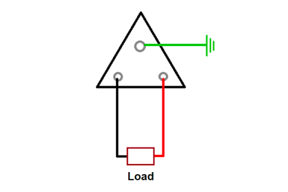
Refer to the below image for more information. As discussed earlier, the cable has three layers – grey color is the conductor, brown color is the insulation, and green color is the sheath.
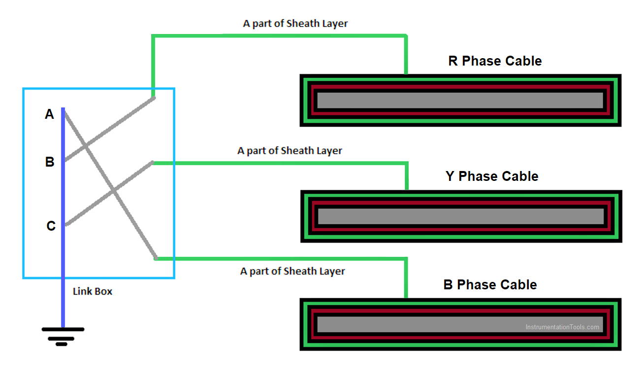
A part of the sheath layer is taken from each of the phases and is connected to the sheath bonding cable and this cable goes inside the link box.
This sheath bonding cable is connected to the bus bar links inside the Link Box which finally makes the sheath connected to the grounding earth causing the sheath circuit to get open-circuited.
This open circuit will make the leakage current from the sheath to near zero. The voltage will be induced, but if there is no current, then there will be no conduction path.
Link boxes are installed at every set of distances of the cable layout from the start of the distribution source to the end destination of power distribution. This helps in minimizing the losses to a very great extent and provides almost zero loss power at the receiver end.
If you see the image, the cable layout runs continuously; only parts of the sheath are cut at regular interval distances and fed to the link box. Link boxes are sealed, weatherproof enclosure boxes for bonding cable earth and joints/terminations.
Types of Link Boxes
Link boxes can be configured as into mainly two types –
- single bonding and
- cross bonding.
Applications of Link Box
One more application of the link box is as a voltage limiter.
Sheath voltage limiters are used so that transient over-voltages, due to lightning or switching surges, does not cause any breakdown of the cable system.
If you liked this article, then please subscribe to our YouTube Channel for Instrumentation, Electrical, PLC, and SCADA video tutorials.
You can also follow us on Facebook and Twitter to receive daily updates.
Read Next: