Inst ToolsInst ToolsInst Tools
  • Courses
  • Automation
    • PLC
    • Control System
    • Safety System
    • Communication
    • Fire & Gas System
  • Instrumentation
    • Design
    • Pressure
    • Temperature
    • Flow
    • Level
    • Vibration
    • Analyzer
    • Control Valve
    • Switch
    • Calibration
    • Erection & Commissioning
  • Interview
    • Instrumentation
    • Electrical
    • Electronics
    • Practical
  • Q&A
    • Instrumentation
    • Control System
    • Electrical
    • Electronics
    • Analog Electronics
    • Digital Electronics
    • Power Electronics
    • Microprocessor
  • Request
Search
  • Books
  • Software
  • Projects
  • Process
  • Tools
  • Basics
  • Formula
  • Power Plant
  • Root Cause Analysis
  • Electrical Basics
  • Animation
  • Standards
  • 4-20 mA Course
  • Siemens PLC Course
Reading: Calculate Temperature Transmitter Output
Share
Notification Show More
Font ResizerAa
Inst ToolsInst Tools
Font ResizerAa
  • Courses
  • Design
  • PLC
  • Interview
  • Control System
Search
  • Courses
  • Automation
    • PLC
    • Control System
    • Safety System
    • Communication
    • Fire & Gas System
  • Instrumentation
    • Design
    • Pressure
    • Temperature
    • Flow
    • Level
    • Vibration
    • Analyzer
    • Control Valve
    • Switch
    • Calibration
    • Erection & Commissioning
  • Interview
    • Instrumentation
    • Electrical
    • Electronics
    • Practical
  • Q&A
    • Instrumentation
    • Control System
    • Electrical
    • Electronics
    • Analog Electronics
    • Digital Electronics
    • Power Electronics
    • Microprocessor
  • Request
Follow US
All rights reserved. Reproduction in whole or in part without written permission is prohibited.
Inst Tools > Blog > Formulas > Calculate Temperature Transmitter Output

Calculate Temperature Transmitter Output

Last updated: April 20, 2019 1:00 pm
Editorial Staff
Formulas Temperature Measurement
No Comments
Share
3 Min Read
SHARE

An electronic  temperature transmitter is ranged  50 to 140 degrees  Fahrenheit and  has  a 4-20 mA output  signal.   Calculate  the  current output  by this  transmitter if the  measured  temperature is 79 degrees Fahrenheit.
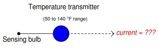
Temperature Transmitter Formula

We are solving this problem using standard 4-20mA conversion Formula. Click here for formula

First, we will set up a linear equation describing  this temperature transmitter’s function:
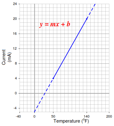
Temperature Transmitter Graph

Calculating and substituting the slope (m)  value for this equation, using the full rise-over-run  of the linear function:

Transmitter span

The y-intercept value will be different  for this example than it was for previous examples,  since the measurement range is not zero-based.  However, the procedure  for finding this value is the same– plug any corresponding  x and  y values into the equation and  solve for b.  In this case, I will use the values of 4 mA for y and 50 o F for x:
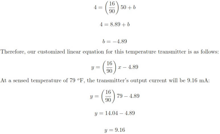
Temperature Transmitter formula conversion

We may apply the same alternative method of solution to this problem as we did for the flowmeter example:   first  converting  the process  variable  into  a  simple  “per  unit” ratio  or  percentage  of measurement range,  then using  that percentage to calculate current in milliamps.

The  “tricky” aspect  of this example is the fact the temperature measurement range does not begin at zero.

Converting  79 deg F  into  a  percentage  of a  50-140 deg F  range  requires  that we first  subtract the live-zero value, then divide by the span:

Temperature Transmitter calculation

Again,  we arrive  at the exact  same figure for transmitter output current:  9.16 milliamps  at a measured temperature of 79 o F.

The  choice to calculate  transmitter current  by first  setting  up  a “customized”  linear  equation for the transmitter in question  or by  converting  the measured  value  into  a percentage  and  using a “standard” linear  equation for current is arbitrary.

Either method  will produce  accurate results, although it could be argued that the “customized equation” approach may save time if many different current values must be calculated.

We can also solve the problem using direct formula. Click here for formula

Articles You May Like :

PLC Example with Switches

Flow Meter Turndown Ratio

Fieldbus Transmitter Calibration

Relationship of Temperature Scales

Formula – 4-20ma from percentage
Don't Miss Our Updates
Be the first to get exclusive content straight to your email.
We promise not to spam you. You can unsubscribe at any time.
Invalid email address
You've successfully subscribed !

Continue Reading

How to Select Right Thermocouple & Thermowell ?
Standard 4 to 20 mA Conversion Formula
Thermowell Outer Diameter Larger than Nozzle Inside Diameter?
How is Pressure Drop Calculated through a Valve ?
Thermocouple Construction
Ambient Temperature Effects on RTD
Share This Article
Facebook Whatsapp Whatsapp LinkedIn Copy Link
Share
Leave a Comment

Leave a Reply Cancel reply

Your email address will not be published. Required fields are marked *

Stay Connected

128.3kFollowersLike
69.1kFollowersFollow
210kSubscribersSubscribe
38kFollowersFollow

Categories

Explore More

Temperature Coefficient of Resistance (α)
RTD Wheatstone Bridge Circuits
Bridge Circuit Construction
4-20mA Transmitters Calculations
Calculate Temperature Coefficient of RTD
Temperature Error of 2-Wire, 3-Wire & 4-Wire RTD
Response Time Test of RTD and Thermocouple
Calibration of Temperature Sensor with Indicator

Keep Learning

Temperature Sensors Questions

Questions on Thermocouple and Pyrometer

Temperature Transmitter Foundation Fieldbus Configuration

Foundation Fieldbus Temperature Transmitter Configuration

Scaling Sensor Output to Engineering Units

Scaling Sensor Output to Engineering Units

Temperature Sensors Interview Questions

Temperature Sensors Interview Questions

Filled-bulb Temperature Measurement

Filled-bulb Temperature Sensors

Relationship between Temperature Scales

Relationship between Temperature Scales

Temperature Scanner

Applications of Temperature Scanner

Thermovcouple Circuit

Thermocouple and its Principle

Learn More

Filters in Compressors

Filters in Compressors

Free Download PLC Book

Free Download Programmable Logic Controller (PLC) Book

Fiber Optic Measurement Techniques

Fiber Optic Measurement Multiple Choice Questions (MCQ)

Tuning a Liquid Level Process Control Loop - 1

Tuning a Liquid Level Process Control Loop

Nameplate Markings

Explosive Atmospheres & Hazardous Classification

CNC Machining vs 3D Printer

CNC Machining vs 3D Printer – What is the difference?

Automatic Coffee Machine

Automatic Coffee Vending Machine – PLC Logic Programming

Thermocouple simulator

Problems of Reference Junction Compensation : Thermocouples

Menu

  • About
  • Privacy Policy
  • Copyright

Quick Links

  • Learn PLC
  • Helping Hand
  • Part Time Job

YouTube Subscribe

Follow US
All rights reserved. Reproduction in whole or in part without written permission is prohibited.
Welcome Back!

Sign in to your account

Username or Email Address
Password

Lost your password?