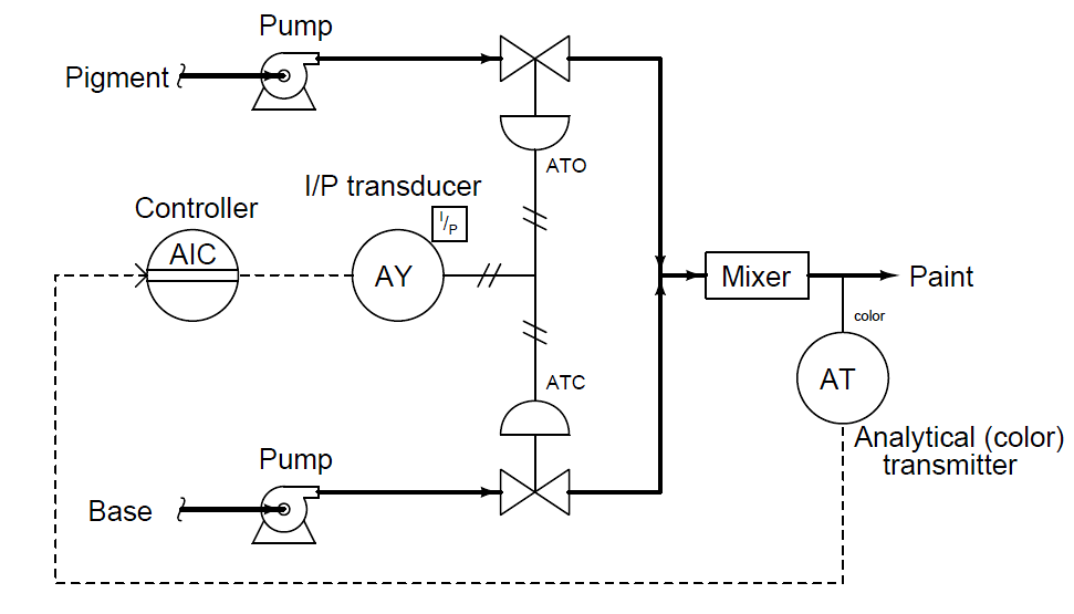
The first type of control valve sequencing is a mode where two valves serve to proportion a mixture of two fluid streams, such as this example where base and pigment liquids are mixed together to form colored paint:
Complementary Control Valve Sequence

Both base and pigment valves operate from the same 3 to 15 PSI pneumatic signal output by the I/P transducer (AY), but one of the valves is Air-To-Open while the other is Air-To-Close.
The following table shows the relationship between valve opening for each control valve and the controller’s output:

An alternative expression for this split-range valve behavior is a graph showing each valve opening as a colored stripe of varying width (wider representing further open).
For this particular mode of split-ranging, the graph would look like this:

With this form of split-ranging, there is never a condition in the controller’s output range where both valves are fully open or fully shut. Rather, each valve complements the other’s position (Note 1).
Note 1 : In mathematics, a “complement” is a value whose sum with another quantity always results in a fixed total. Complementary angles, for instance, always add to 90 deg (a right angle).
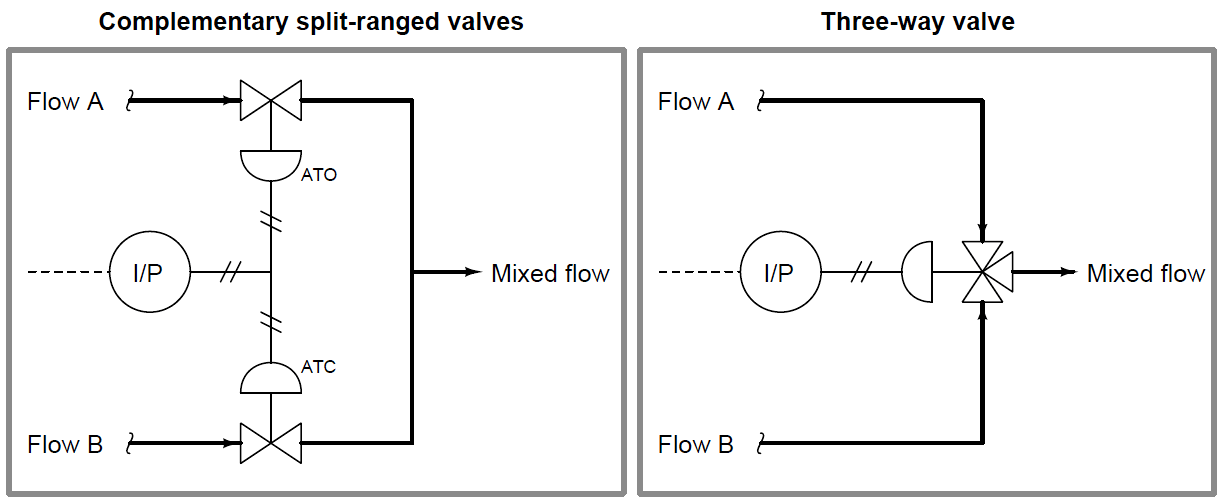
An alternative to complementary valve sequencing in a process where two fluid streams mix (or diverge) is to use one three-way valve (Note2) rather than a pair of two-way valves:
Note 2 : Also known as a mixing valve or a diverting valve, depending on how it is applied to process service.

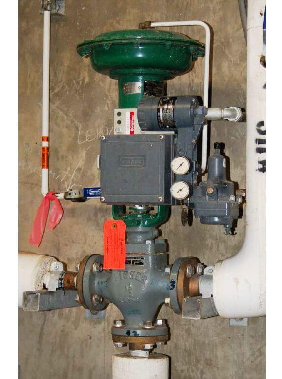
A photograph of a three-way globe valve mixing hot and cold water to control temperature is shown here:

Also Read : Control Valve Interview Questions