Actuator :
By themselves, valves cannot control a process. Manual valves require an operator to position them to control a process variable. Valves that must be operated remotely and automatically require special devices to move them. These devices are called actuators.
Actuators may be pneumatic, hydraulic, or electric solenoids or motors.
Pneumatic Actuators :
A simplified diagram of a pneumatic actuator is shown in Figure 1. It operates by a combination of force created by air and spring force. The actuator positions a control valve by transmitting its motion through the stem.
A rubber diaphragm separates the actuator housing into two air chambers. The upper chamber receives supply air through an opening in the top of the housing.

Figure 1 : Pneumatic Actuator: Air-to-Close/Spring-to-Open
The bottom chamber contains a spring that forces the diaphragm against mechanical stops in the upper chamber. Finally, a local indicator is connected to the stem to indicate the position of the valve.
The position of the valve is controlled by varying supply air pressure in the upper chamber. This results in a varying force on the top of the diaphragm. Initially, with no supply air, the spring forces the diaphragm upward against the mechanical stops and holds the valve fully open.
As supply air pressure is increased from zero, its force on top of the diaphragm begins to overcome the opposing force of the spring. This causes the diaphragm to move downward and the control valve to close. With increasing supply air pressure, the diaphragm will continue to move downward and compress the spring until the control valve is fully closed.
Conversely, if supply air pressure is decreased, the spring will begin to force the diaphragm upward and open the control valve. Additionally, if supply pressure is held constant at some value between zero and maximum, the valve will position at an intermediate position. Therefore, the valve can be positioned anywhere between fully open and fully closed in response to changes in supply air pressure.
A positioner is a device that regulates the supply air pressure to a pneumatic actuator. It does this by comparing the actuator’s demanded position with the control valve’s actual position.
The demanded position is transmitted by a pneumatic or electrical control signal from a controller to the positioner. The pneumatic actuator in Figure 1 is shown in Figure 2 with a controller and positioner added.
Also Read : Control Valve Positioner Principle
The controller generates an output signal that represents the demanded position. This signal is sent to the positioner. Externally, the positioner consists of an input connection for the control signal (4-20mA), a instrument supply air input connection, a supply air output connection, a supply air vent connection, and a feedback linkage.
Internally, it contains an intricate network of electrical transducers, air lines, valves, linkages, and necessary adjustments. Other positioners may also provide controls for local valve positioning and gauges to indicate supply air pressure and control air pressure (for pneumatic controllers – old controlling methods).

Figure 2 : Pneumatic Actuator with Controller and Positioner
In Figure 2, the controller responds to a deviation of a controlled variable from setpoint and varies the control output signal accordingly to correct the deviation. The control output signal is sent to the positioner, which responds by increasing or decreasing the supply air to the actuator.
Positioning of the actuator and control valve is fed back to the positioner through the feedback linkage. When the valve has reached the position demanded by the controller, the positioner stops the change in supply air pressure and holds the valve at the new position. This, in turn, corrects the controlled variable’s deviation from setpoint.

Image Credits : Fisher
For example, as the control signal increases, a valve inside the positioner admits more supply air to the actuator. As a result, the control valve moves downward. The linkage transmits the valve position information back to the positioner.
This forms a small internal feedback loop for the actuator. When the valve reaches the position that correlates to the control signal, the linkage stops supply air flow to the actuator.
This causes the actuator to stop. On the other hand, if the control signal decreases, another valve inside the positioner opens and allows the supply air pressure to decrease by venting the supply air. This causes the valve to move upward and open. When the valve has opened to the proper position, the positioner stops venting air from the actuator and stops movement of the control valve.
An important safety feature is provided by the spring in an actuator. It can be designed to position a control valve in a safe position if a loss of supply air occurs. On a loss of supply air, the actuator in Figure 2 will fail open.
This type of arrangement is referred to as “air-to-close, spring-to-open” or simply “fail-open.” Some valves fail in the closed position. This type of actuator is referred to as “air-to-open, spring-to-close” or “fail-closed.” This “fail-safe” concept is an important consideration in hazardous areas..
Advantages of Pneumatic Actuators
The benefits of pneumatic actuators come from their simplicity.
Pneumatic actuators’ typical applications involve areas where the conditions involve extreme temperatures, a typical temperature range is -40°F to 250°F.
In terms of safety and inspection, using air and pneumatic actuators avoids using hazardous materials. They also meet explosion protection and machine safety requirements because they create no magnetic interference due to the lack of motors.
Pneumatic actuators are also lightweight, require minimal maintenance, and have durable components that make pneumatics a cost effective method of power.
Disadvantages of Pneumatic Actuators
Pressure losses and compressibility of air make pneumatics less efficient than other methods. Compressor and air delivery limitations mean that operations at lower pressures will have lower forces and slower speeds.
To be truly efficient, pneumatic actuators must be sized for a specific job. Hence, they cannot be used for other applications.
Even though air is readily available, it can be contaminated by oil or lubrication, leading to downtime and maintenance. Companies still have to pay for compressed air, making it a consumable, along with the compressor and line maintenance costs.
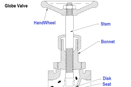
Control Valve Parts


Image Courtesy : watson mcDaniel
Also Read : Control Valves Interview Questions


Is it possible to have impellar type rotary valve with pneumatic Actuator?
Please use there Butterfly Magnetics Control Valve Is the better Performance. I hope then You Happy .