Inst ToolsInst ToolsInst Tools
  • Courses
  • Automation
    • PLC
    • Control System
    • Safety System
    • Communication
    • Fire & Gas System
  • Instrumentation
    • Design
    • Pressure
    • Temperature
    • Flow
    • Level
    • Vibration
    • Analyzer
    • Control Valve
    • Switch
    • Calibration
    • Erection & Commissioning
  • Interview
    • Instrumentation
    • Electrical
    • Electronics
    • Practical
  • Q&A
    • Instrumentation
    • Control System
    • Electrical
    • Electronics
    • Analog Electronics
    • Digital Electronics
    • Power Electronics
    • Microprocessor
  • Request
Search
  • Books
  • Software
  • Projects
  • Process
  • Tools
  • Basics
  • Formula
  • Power Plant
  • Root Cause Analysis
  • Electrical Basics
  • Animation
  • Standards
  • 4-20 mA Course
  • Siemens PLC Course
Reading: Globe Valve Body Design
Share
Notification Show More
Font ResizerAa
Inst ToolsInst Tools
Font ResizerAa
  • Courses
  • Design
  • PLC
  • Interview
  • Control System
Search
  • Courses
  • Automation
    • PLC
    • Control System
    • Safety System
    • Communication
    • Fire & Gas System
  • Instrumentation
    • Design
    • Pressure
    • Temperature
    • Flow
    • Level
    • Vibration
    • Analyzer
    • Control Valve
    • Switch
    • Calibration
    • Erection & Commissioning
  • Interview
    • Instrumentation
    • Electrical
    • Electronics
    • Practical
  • Q&A
    • Instrumentation
    • Control System
    • Electrical
    • Electronics
    • Analog Electronics
    • Digital Electronics
    • Power Electronics
    • Microprocessor
  • Request
Follow US
All rights reserved. Reproduction in whole or in part without written permission is prohibited.
Inst Tools > Blog > Control Valves > Globe Valve Body Design

Globe Valve Body Design

Last updated: March 21, 2019 3:50 pm
Editorial Staff
Control Valves
No Comments
Share
3 Min Read
SHARE

Globe Valve Body Design

The three primary body designs for globe valves are

Contents
Globe Valve Body DesignZ-Body DesignY-Body DesignAngle Valve Design
  1. Z-body,
  2. Y-body, and
  3. Angle.

Z-Body Design

The simplest design and most common for water applications is the Z-body.

The Z-body is illustrated in below Figure.
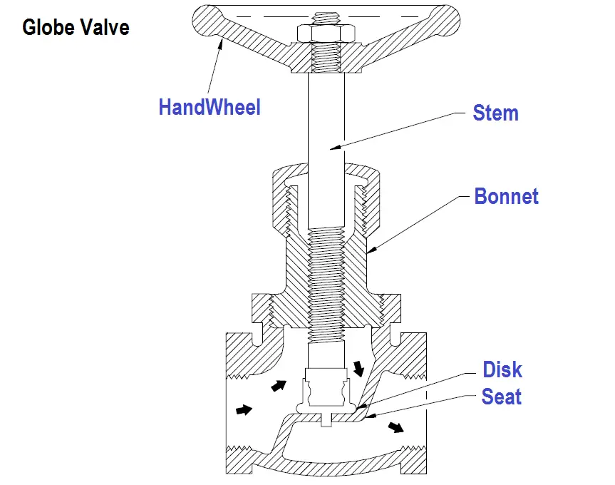
Globe Valve Z-Body Parts

Figure : Z-Body Globe Valve

For this body design, the Z-shaped diaphragm or partition across the globular body contains the seat. The horizontal setting of the seat allows the stem and disk to travel at right angles to the pipe axis.

The stem passes through the bonnet which is attached to a large opening at the top of the valve body. This provides a symmetrical form that simplifies manufacture, installation, and repair.

Y-Body Design

Below Figure illustrates a typical Y-body globe valve. This design is a remedy for the high pressure drop inherent in globe valves. The seat and stem are angled at approximately 45°.

The angle yields a straighter flowpath (at full opening) and provides the stem, bonnet, and packing a relatively pressure resistant envelope.
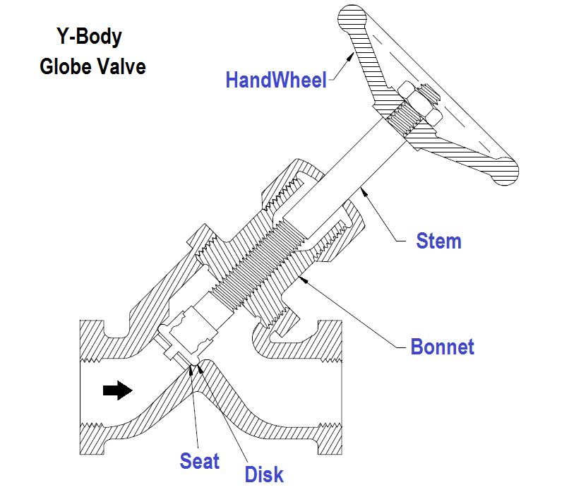
Globe Valve Y-Body Parts

Figure : Y-Body Globe Valve

Y-body globe valves are best suited for high pressure and other severe services. In small sizes for intermittent flows, the pressure loss may not be as important as the other considerations favoring the Y-body design.

Hence, the flow passage of small Y-body globe valves is not as carefully streamlined as that for larger valves.

Angle Valve Design

The angle body globe valve design, illustrated in Below Figure, is a simple modification of the basic globe valve.

Having ends at right angles, the diaphragm can be a simple flat plate. Fluid is able to flow through with only a single 90° turn and discharge downward more symmetrically than the discharge from an ordinary globe.
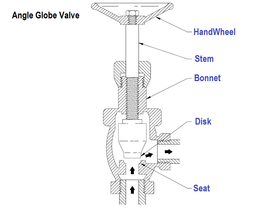
Angle Globe Valve Parts

Figure : Angle Globe Valve

A particular advantage of the angle body design is that it can function as both a valve and a piping elbow. For moderate conditions of pressure, temperature, and flow, the angle valve closely resembles the ordinary globe.

The angle valve’s discharge conditions are favorable with respect to fluid dynamics and erosion.

Articles You May like :

Valve Handwheel Types

Control Valves MCQ

Shutdown Valve Parts

Spring Pneumatic Actuators

What is Reducing Valve ?

Don't Miss Our Updates
Be the first to get exclusive content straight to your email.
We promise not to spam you. You can unsubscribe at any time.
Invalid email address
You've successfully subscribed !

Continue Reading

Calculate Control Valve Stem Position
Relative Flow Capacity of a Valve
Calculate Flow Coefficient Kv of Solenoid Valve
Control Valve Questions and Answers
Top 80+ Valve Questions and Answers
Trip Valve Principle
Share This Article
Facebook Whatsapp Whatsapp LinkedIn Copy Link
Share
Leave a Comment

Leave a Reply Cancel reply

Your email address will not be published. Required fields are marked *

Stay Connected

128.3kFollowersLike
69.1kFollowersFollow
210kSubscribersSubscribe
38kFollowersFollow

Categories

Explore More

Different Control Valve Flow Characteristics
Solenoid Valves Types & Functions
Control Valve Trim Characteristics
Motor Operated Valve Problems and Troubleshooting
Why we Require Dual SOV on a Control Valve?
Comparison of Gate Valves and Globe Valves
How do you do control valve sizing in Layman’s terms?
Valve Characteristics – Quick Opening, Linear & Equal Percentage

Keep Learning

What is Instrument Air Manifold

What is Instrument Air Manifold ?

trip solenoid installed on a control valve appears

SIS Final Control Elements

Chocked flow

Control Valve Cavitation and Flashing

Breather Valve Working Principle

Breather Valve Working Principle

What is Swing Check Valve ?

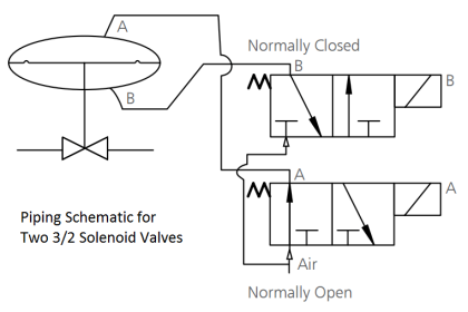
Piping Schematic for Two Solenoid Valves Double Acting

Different Types of Control Valve Actuators

Solenoid Valve

Solenoid Valve Troubleshooting Practices

Air Lock Relay Working Principle

Control Valve Air Lock Relay Working Principle

Learn More

Cable Bending Radius

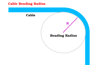
What is Cable Bending Radius? – Definition & Calculation

Selection of Weighing Balance

Selection of Weighing Balance and Weight for Calibration

Pressure Gauge Accessories

Pressure Gauge Accessories Questions and Answers

Pressure transmitter Calibration Setup

Instruments Calibration Procedures

Electrical Machines Questions and Answers

Three Phase Induction Motor Power Factor Control

Valve Positioner Torn apart

Pipeline Shakes Torn apart Valve Positioners

Multistage Flash Drums Erratic Level Readings

Multistage Flash Drums Erratic Level Readings

PLC Technique for IO Mapping

PLC Techniques for I/O Mapping

Menu

  • About
  • Privacy Policy
  • Copyright

Quick Links

  • Learn PLC
  • Helping Hand
  • Part Time Job

YouTube Subscribe

Follow US
All rights reserved. Reproduction in whole or in part without written permission is prohibited.
Welcome Back!

Sign in to your account

Username or Email Address
Password

Lost your password?