A single element control system is one with just one control input, a two element control system is one with two control inputs, etc.
A three-element boiler water level control system is one which typically uses the measured water level, the steam flowrate from the boiler, and the water flowrate into the boiler to regulate the flow of water into the boiler.
Although you might think that measuring water level alone is sufficient, you have to bear in mind that the boiler water contains lots of steam bubbles.
Bubble size is affected by pressure, so if a boiler experiences a sudden extra demand for steam, its pressure drops.
The drop in pressure causes the steam bubbles in the boiler water to expand, and the level measurement can show an increase in level.
The false high reading makes the water level control system reduce the flow of water into the boiler. Once boiler pressure is restored the steam bubbles contract, and the measured water level drops suddenly.
The level control system responds to this by increasing the flow of water into the boiler, which effectively deluges the boiler with relatively cold water, and boiling is arrested.
Some of the steam bubbles in the boiler water collapse, and the boiler water level drops significantly – possibly to a low-level alarm or lockout.
By adding water and steam flow measurement into the control system, we can identify any major disparity between the two, and make a compensation to the measured water level.
This means that any transient peak demands on the boiler are recognized as such, and the feedforward control is appropriately applied.
Incidentally, it is possible to achieve the same results using a two-element control system (level and steam flow), but it is easier to commission three-element systems.
Three-element boiler water level control systems are sometimes refereed to as “feed forward” control.
This is because the system identifies a transient high demand for steam before it has any effect on the boiler water level, and therefore starts to put extra water into the boiler in anticipation of demand.
In this control philosophy, there are three process variables.
1. Boiler Level,
2. Feed water flow and
3. Steam Flow to control boiler Drum Level.
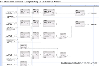
Boiler Three Element Controller

Understanding of diagram :

Here, LT1, LT2 and LT3 are three different Level transmitter. reason for using three level transmitters is simple that, in case of failure of any transmitter(s), control wont be affected. LT is average of three LTs.
Water density changes with pressure. So density compensation is there for every level transmitter.
LIC is first PID block with LT as process variable.
FT1 is the steam flow leaving the steam drum. Here we have done pressure and temperature correction.
Output of LIC and FT1 goes to one calculation block. Output of this block is our remote set point for Flow controller (FIC).
FT2 is feed water flow to the boiler drum and process variable for FIC.
SS is selector switch. By this controlling philosophy can be selected either single or three element.
FCV is feed flow control valve.
Types of Control:
Single Element Control:
During lower boiler loads or <30% steam flow, drum level signal LT and the fixed local set point LSP are compared in LIC and the controller output is fed to feed water control valve FCV
Three Element Control:
The steam flow signal sensed by the steam flow transmitter FT1 acts as a feed forward signal and takes care of the shrink & swell effect.
The steam flow transmitter is connected across flow nozzle, and the signal is then compensated for pressure and temperature.
LIC is the primary controller in the three element level control function. When the steam drum water level is below the set point, controller LIC will further increase the remote set point of the feed water flow controller to increase the feed water flow. When the level is too high the reverse action will take place.
The Level controller LIC output signal is added with the compensated steam flow signal at calculation block.
The following equation is implemented in summing block
Remote SP for (FIC) % = (LIC) O/P + Steam Flow (FT1) PV in % – 50%
FIC is the secondary controller in the three element level control. When the feed water flow is below the set point, controller FIC will further increase the feed water flow by opening the feed water control valve. When the flow is too high the reverse action will take place.


Simply Simple.
Nice explanation.
Very simple and easily understandable description.
Thanks.
The whole instrumentation topics/articles explained in very simply way & easy to understand…I salute you love you sir…
I don’t have words to express about the explanation on any topic which you mention.. beautiful mind-blowing
Thanking you for your support & motivation.
Regards,
Junaid
All are good how to take hard copy all theory…
Hello Raj, Open Website in Desktop/PC and then click Print Option which is available under the Article Heading to save in PDF. Thanks
So simple and nice explanation .Thank u sir
pls explain working principle of burner
Sir,
Very nice explanation about all topics. So please give me density compensation Formula for drum level with example.
Nice & simple explaination. Its easy to understand the priciple of 3-element loop.
very good explaination.
really ultimate explanation…God bless u
Sir,very gud explanation
Ultimate site regarding all Instrumentation and Electrical topic,i always follow when i study of Instrumentation or Electrical.
Thank you for your post, but could you please explain to me what the figure 50% means?
Just splendid
hello guys, I’m facing a trouble with 4 marshaling cabinets: Earth leakage fault appeared at the beginning of power-up on displays of VIGIBLOC inside cabinets .
Hello sir,
This is durga prasad regala,control & instrumentation .
in our plant we are using DP level transmitter for one tank,this tank is closed tank and under vacuum ,so we are facing problem with this level measurement ,can give solution for this tank,how to over come from this issue .
thanking you sir
Dear Mr. Durga,
It is recommended to use GWR (Guided wave radar) type level transmitters for such applications.
Very good response & reliable!
Pawan Khetan
Well…..there will be a natural level difference between the right and the left side of the drum.
So anyway you need minimum two transmitters ;one each mounted on each side and it can be averaged or one transmitter can be considered in case of other transmitter failure using selector switch on xmr failure.
However, since we need two out of three drum level signals for reliable drum level low condition for boiler trip,we mount two transmitters on one side and the third one on the other side.
Hence transmitter failure is not the only reason for using three transmitters and averaging
All of this topics here are explain so nicely , Its really helpful
Hello Sir,
Thanks for the detailed explanation. i have a query on the below formulae
The following equation is implemented in summing block
Remote SP for (FIC) % = (LIC) O/P + Steam Flow (FT1) PV in % – 50%
Why the bias signal of -50% is included in the above equation?
is it to keep the level at 50% minimum for the tube protection?
thanks in advance.
sir, is it right to say that
single element is feedback system
two element is feed forward system and
three element is cascade system ?
Please sir can you explain how to do density compensation?
Not bad, but better if you have 2 LICs. 1st one is for 1-element, 2nd one is the auxiliary controller for the flow controller with calc block. The output from this LIC is scaled from 50% to -50% and used in calc block.
This value must be scaled to the double possible bfw mass flow.
Then you scale the steam volume flow to a mass flow equivalent of water. These 2 values are summed and the setpoint of bfw flow controller. Then you must configure MV tracking of the 2 controllers to have a bumpless switchover. For tuning make 1st level smooth (low p, smooth I). Set 2nd level to p controller with p = 1.25.
Your boiler will run like a 12 cylinder car.
I have a doubt, Feedwater Flow transmitter to be erected after FCV or Before please suggest me
Very useful….
Sir, will you explain me why we can’t use steam preassure in three element control system. while we use always (Drum level, steam flow, feed water flow) but i want to use ( Drum level, steam pressure, feed water flow).