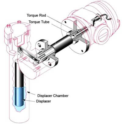
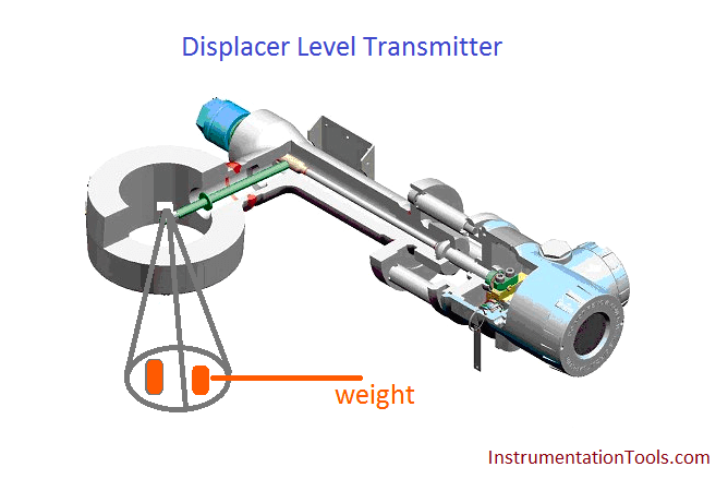
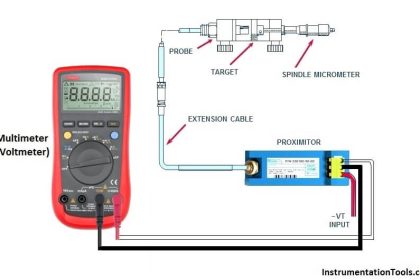
A displacer level transmitter consists of a displacer element which is suspended from a hanger with a torque tube which is connected to the transmitter head.
The displacer element is designed to be heavier than the liquid in which it is being used so that, even when fully immersed in the liquid, so it still exerts a downward force on the hanger.
Displacer Level Transmitter Dry Calibration
As the liquid in the vessel rises to cover the element, a buoyancy force is created which is equal to the weight of the liquid displaced by the element (Archimedes’s principle). This is seen by the transmitter as an effective reduction of the hanging weight of the element, and, as the displacer element hanging weight is proportional to the liquid level around it, the electronics in the transmitter head can give readout of liquid level.
The Archimedes Principle:
Archimedes principle states that the buoyant force exerted on a body immersed in a fluid is equal to the weight of the fluid the body displaces
Advantages
Displacer transmitters are widely used. Able to operate at extremes of pressure and temperature, and commonly used to measure interface level measurement.
Limitations
The accuracy of the level measurement is dependent upon correct calibration of the instrument at operating conditions. If these conditions would change (Density), the level reading will be incorrect. Torque tube displacer transmitters in particular require regular maintenance and calibration checks, and can suffer from damage during surge conditions.
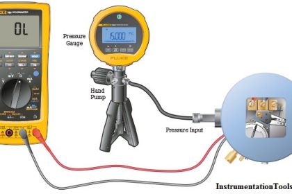
Dry Calibration of level transmitter:
Dry Calibration with Weights for liquid level :
Suppose level transmitters which float weight is 3.0 kg and float length and diameter is 40 cm and 8 cm. Calculate the weight for dry calibration.
Density of water: 1 gm/cm3
Length of float (L): 40 cm
Diameter of float (D): 8 cm
Density of water (d): 1 gm/cm3
Weight of float: 3.0 kg = 3000 gm
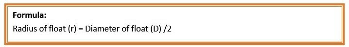
So, r = 8/2 cm = 4 cm
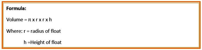
so, Volume = = 3.14 x 4 x 4 x 40 = 2009.6 cm3

So, Total Weight at 0% = 3000 gm = 4 ma
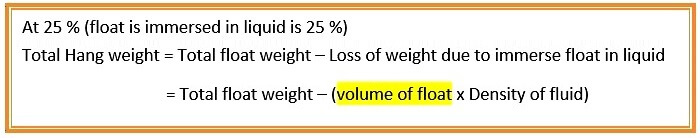
So, Total Weight at 25% =
= 3000 – (3.14 x 4 x 4 x10 x 1)
= 300 – 502.4
= 2497.6 gm = 8 ma
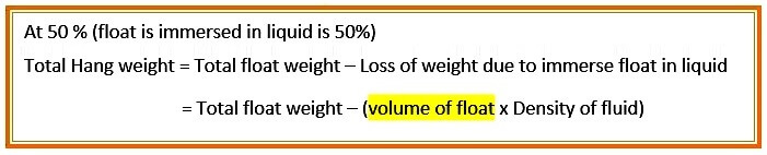
So, Total Weight at 50% = 3000 – (3.14 x 4 x 4 x20 x 1) = 300 – 1004.8 = 1995.2 gm = 12 ma
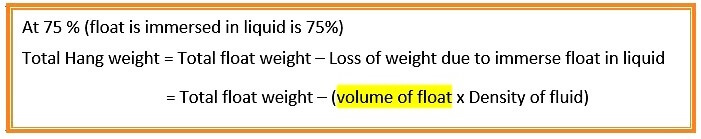
So, Total Weight at 75% =
= 3000 – (3.14 x 4 x 4 x30 x 1)
= 300 – 1507.2
= 1492.8 gm = 16 ma
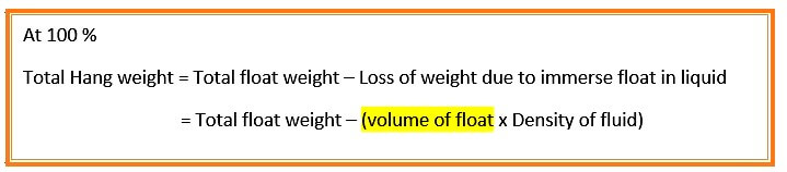
So, Total Weight at 100% =
= 3000 – (3.14 x 4 x 4 x 40 x 1)
= 3000 – (2009.6 x 1)
= 990.4 gm = 20 ma
The 4ma and 20mA equivalents of weights are used to configure the displacer level transmitter
Interface level is measured with dry weight calibration
Suppose level transmitters which float weight is 3.0 kg and float length and diameter is 40 cm and 8 cm. Calculate the weight for dry calibration. Where two process fluids is present
Density of higher fluid (d1)(Liquid): 0.8 gm/cm3
Density of lighter fluid (d2)(Gas) : 0.15 gm/cm3
Length of float (L): 40 cm
Diameter of float (D): 8 cm
Density of water (d): 1 gm/cm3
Weight of float: 3.0 kg = 3000 gm
So, r = 8/2 cm = 4 cm

So, Total Float immersed at 0% =
= 3000 – (3.14 x 4 x 4 x40 x 0.15)
= 3000 – 301.44
= 2698.56 gm = 4 ma
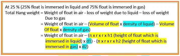
So, Total Float immersed at 25% =
= 3000 – (3.14 x 4 x 4 x 10 x 0.80) – (3.14 x 4 x4 x 30 x 0.15)
= 3000 – (401.92) – (226.08)
= 2372 gm = 8 ma

So, Total Float immersed at 50 % =
= 3000 – (3.14 x 4 x 4 x 20 x 0.80) – (3.14 x 4 x4 x 20 x 0.15)
= 3000 – (803.84) – (150.72)
= 2045.44 gm = 12 ma
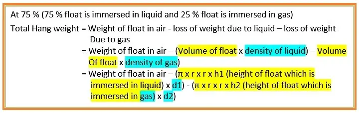
So, Total Float immersed at 75% =
= 3000 – (3.14 x 4 x 4 x 30 x 0.80) – (3.14 x 4 x4 x 10 x 0.15)
= 3000 – (1205.76) – (75.36)
= 1718.88 gm = 16 ma
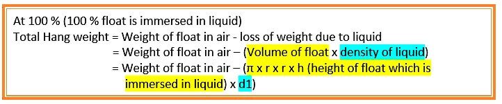
So, Total Float immersed at 100 % =
= 3000 – (3.14 x 4 x 4 x 40 x 0.80)
= 3000 – (1607.68)
= 1392.32 gm = 20 ma
The 4ma and 20mA equivalents of weights are used to configure the displacer level transmitter


Sir,
In First example
In 25% of Toal weight and 50% of Total weight is equal how to change output (ma) sir.
In First example
25%,75%,100% volume of float equation height (h) is change why sir.
Hi,
For your first question, yes there is a mistake, at 25% total float immersed should be 10 cm not 20 cm.
For your second question , yes the height here change because it is the height of the portion of the float that is immersed : at 0% it means the height of the float immersed is 0 cm ( out of total height 40 cm)
at 25% it is 10 cm
at 50 % it is 20 cm
at 75% it is 30 cm
and at 100% means total height of the float is immersed, i.e 40 cm.
I made a mistake by using the term float, it is a displacer and not float.
Corrected. Author was right, its my mistake during publishing. Thanks for the update.
As per principle which height of displacer is immeresed in fluid only that of part of displacer (weight loss is occured) which is equal to the (volume of displacer × density of fluid). So height will be changed respectively
Dear Mr. Reddy,
Very useful article. Appreciated your work and who are supporting. Keep it up.
It’s a very nice website for instrumentation guys. and it’s like an instrumentation encyclopedia.
Thanks,
Thanks for sharing knowledge