Inst ToolsInst ToolsInst Tools
  • Courses
  • Automation
    • PLC
    • Control System
    • Safety System
    • Communication
    • Fire & Gas System
  • Instrumentation
    • Design
    • Pressure
    • Temperature
    • Flow
    • Level
    • Vibration
    • Analyzer
    • Control Valve
    • Switch
    • Calibration
    • Erection & Commissioning
  • Interview
    • Instrumentation
    • Electrical
    • Electronics
    • Practical
  • Q&A
    • Instrumentation
    • Control System
    • Electrical
    • Electronics
    • Analog Electronics
    • Digital Electronics
    • Power Electronics
    • Microprocessor
  • Request
Search
  • Books
  • Software
  • Projects
  • Process
  • Tools
  • Basics
  • Formula
  • Power Plant
  • Root Cause Analysis
  • Electrical Basics
  • Animation
  • Standards
  • 4-20 mA Course
  • Siemens PLC Course
Reading: Radar Level Transmitter in Briddle level Measurement
Share
Notification Show More
Font ResizerAa
Inst ToolsInst Tools
Font ResizerAa
  • Courses
  • Design
  • PLC
  • Interview
  • Control System
Search
  • Courses
  • Automation
    • PLC
    • Control System
    • Safety System
    • Communication
    • Fire & Gas System
  • Instrumentation
    • Design
    • Pressure
    • Temperature
    • Flow
    • Level
    • Vibration
    • Analyzer
    • Control Valve
    • Switch
    • Calibration
    • Erection & Commissioning
  • Interview
    • Instrumentation
    • Electrical
    • Electronics
    • Practical
  • Q&A
    • Instrumentation
    • Control System
    • Electrical
    • Electronics
    • Analog Electronics
    • Digital Electronics
    • Power Electronics
    • Microprocessor
  • Request
Follow US
All rights reserved. Reproduction in whole or in part without written permission is prohibited.
Inst Tools > Blog > Animation > Radar Level Transmitter in Briddle level Measurement

Radar Level Transmitter in Briddle level Measurement

Last updated: June 5, 2019 12:21 pm
Editorial Staff
Animation How It Works Level Measurement
4 Comments
Share
0 Min Read
SHARE

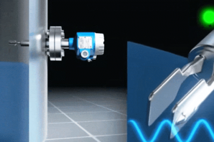
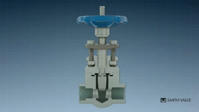
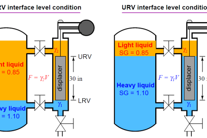
Guided Wave Radar is the ideal choice for measurements in bridles. It is unaffected by density changes, bridle configuration and has no moving parts which minimizes maintenance. This makes it an easy and reliable substitute for displacer technology. General Radar level application & Briddle level application working principles are similar.


Radar Level Transmitter in Briddle level Measurement

Image Courtesy : Endress Hauser

Also Read: Level Measurement Working Principles

Don't Miss Our Updates
Be the first to get exclusive content straight to your email.
We promise not to spam you. You can unsubscribe at any time.
Invalid email address
You've successfully subscribed !

Continue Reading

Deluge Valve Working Principle
Displacer (buoyancy) Level Transmitter Principle, Limitations, Design, Installation & Calibration
Gas chromatograph Working Animation
Laser Level Measurement Principle
Float & Dial Level Gauge Principle
Relay Principle & its Types
Share This Article
Facebook Whatsapp Whatsapp LinkedIn Copy Link
Share
4 Comments
  • Pravin says:
    September 19, 2015 at 9:42 am

    HOW TO DOWNLOAD ANIMATIONS

    Reply
    • S Bharadwaj Reddy says:
      September 19, 2015 at 10:58 am

      You can download directly, right-click and save.

      Reply
  • Nishant Sohani says:
    May 24, 2016 at 3:37 am

    Thanks. nice information

    Reply
  • RAMDANI abdennacer says:
    July 24, 2016 at 5:52 am

    thanks a lot for your important information

    Reply

Leave a Reply Cancel reply

Your email address will not be published. Required fields are marked *

Stay Connected

128.3kFollowersLike
69.1kFollowersFollow
210kSubscribersSubscribe
38kFollowersFollow

Categories

Explore More

Closed tank DP Level Transmitter with wet leg elevation zero remote mount Calibration
How a 4-20mA Transmitter Works?
Capacitance Level Transmitter Animation
Displacer Interface Level Measurement
Two Wire Sensor Working Principle and Animation
Zero Elevation and Zero Suppression in Level Measurement
Displacer Level Sensor Working Animation
Main differences between Sinking and Sourcing Circuits

Keep Learning

AND Gate Logic Animation

Digital Building Blocks – GATES

pressure-gauge-animation

Bourdon Tube Pressure Gauge Working Principle Animation

DP-Transmitter-with-two-seals

DP Transmitter with Two Seals applications

Ultrasonic Level Transmitters Installation

Ultrasonic Level Transmitter Principle, Limitations, Calibration and configuration

Microwave Barrier Level Switch Working Principle

Transparent Level Gauge

Level Indicators Working Principle

Level Transmitters Auto Calibration

DP Level Transmitter Auto Calibration

Conductive Level Measurement Working Principle

Conductive Level Measurement Working Principle

Learn More

Difference between TCP-IP Model and OSI Model

Difference between TCP/IP Model and OSI Model

Which instrument is at fault in this system

Which Instrument is at Fault in this System?

Thermocouple Law of Intermediate Metals

Thermocouples Law of Intermediate Metals

knock-out drum

Applying Probability Laws to a Safety Instrumented System

Measurement and Instrumentation Objective Questions

Measurements & Instrumentation Quiz – Set 3

Calculate the amount of voltage at Thermocouple

Calculate the Voltage across Voltmeters of Thermocouple

Purpose of Instrument Loop Diagrams

Purpose of Loop Diagrams

Glass Cutting and Polishing Machine PLC Automation Solution

Glass Cutting and Polishing Machine: PLC Automation Solution

Menu

  • About
  • Privacy Policy
  • Copyright

Quick Links

  • Learn PLC
  • Helping Hand
  • Part Time Job

YouTube Subscribe

Follow US
All rights reserved. Reproduction in whole or in part without written permission is prohibited.
Welcome Back!

Sign in to your account

Username or Email Address
Password

Lost your password?