A pipe “flange” is a ring of metal, usually welded to the end of a pipe, with holes drilled in it parallel to the pipe center line to accept several bolts:
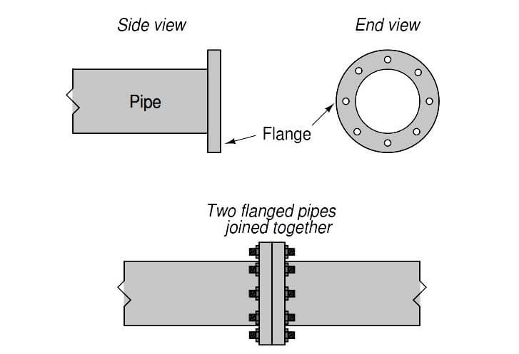
Flange joints are made pressure-tight by inserting a donut-shaped gasket between the flange pairs prior to tightening the bolts. Gaskets are manufactured from materials softer than the flange material. When sandwiched between a pair of flanges, the gasket will be “crushed” between them to seal all potential leak paths.
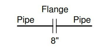
In instrument diagrams such as P&IDs, flanges are denoted by two short parallel lines, both perpendicular to the pipe. The pipe size of the flange is often written near the flange symbol, as is the case with this 8-inch flange symbol shown below:
A photograph showing a Rosemount magnetic flowmeter installed with 4-bolt flange fittings appears here:
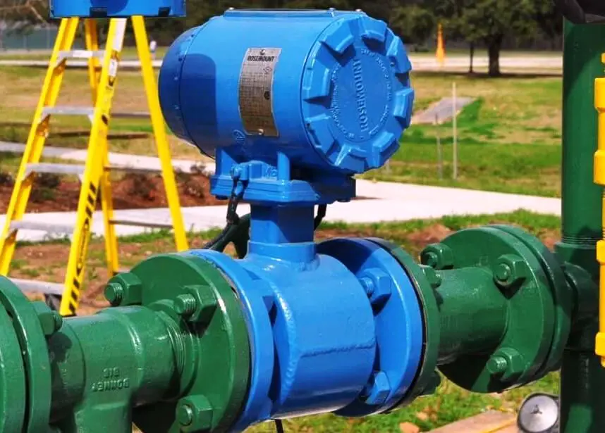
If you examine the flanged connections closely, you can see the gap between the flange faces created by the thickness of the gasket material “sandwiched” between the flange pairs.
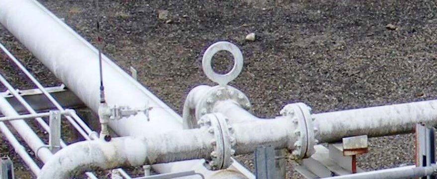
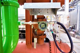
In this next photograph, we see a pair of large pipe flange connections on either end of a relatively short “spool” pipe section. The large number of studs holding each flange set together gives you some indication of the pressure of the fluid within, in this case upwards of 1000 PSI!
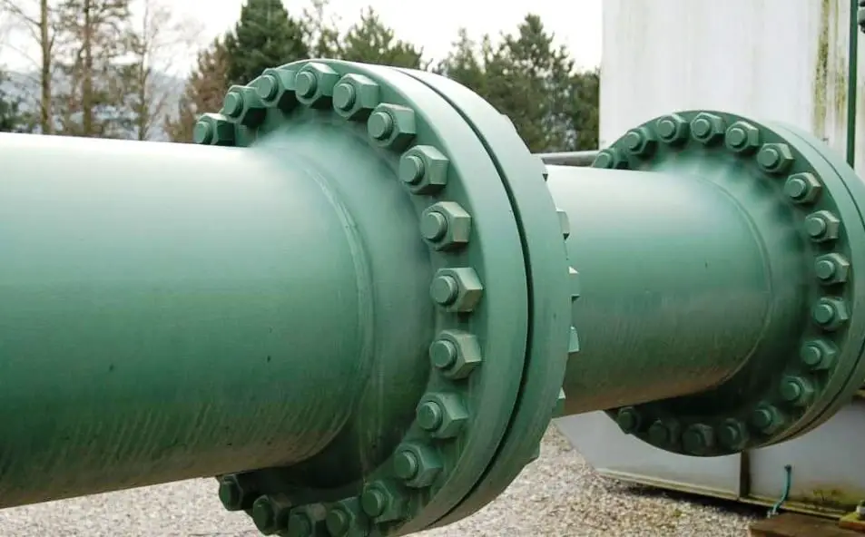
Like the flowmeter flanges shown previously, gaps between the flange ring faces reveal the space occupied by the gasket sealing those flange surfaces together to form a pressure-tight seal.
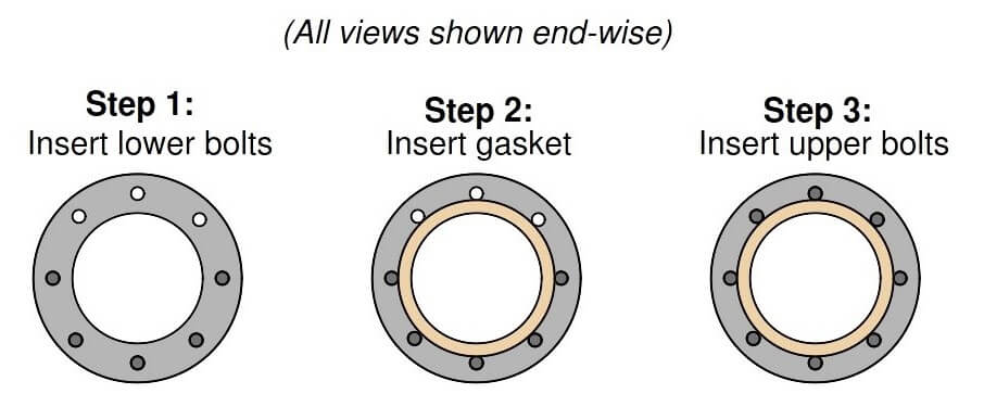
A common method of installing such a flange gasket is to first install only half of the bolts (in the holes lower than the centerline of the pipe), drop the gasket between the flanges, insert the remaining bolts, then proceed to tighten all bolts to the proper torques:
Flanges differ with regard to their sealing design and required gasket type. In the United States, one of the most common flange “face” designs is the raised-face (RF) flange, designed to seal against a gasket by means of a set of concentric grooves machined on the face of the flange. These grooves form a sealing surface with far greater leakage path length than if the faces were smooth, thus discouraging leakage of process fluid under pressure.
Another flange face design is called ring-type joint (RTJ). In this design, a special metal ring sits inside a groove machined into the faces of both mating flanges, crushing and filling that groove when the flanges are properly tightened together. RTJ flanges are typically found on highpressure applications where leakage control is more challenging. The grooves in RTJ flanges must be completely free of foreign material, and well-formed (not distorted) in order to achieve proper sealing.
In the United States, flanges are often rated according to a system of “pressure classes” defined in the ANSI (American National Standards Institute) standard 16.5. These pressure classes are designated by numerical values followed by “pound”, “lb”, or “#”. Common ANSI ratings include the 150#, 300#, 400#, 600#, 900#, 1500#, and 2500# pressure classes. It should be noted that these class numbers do not refer directly to pressure ratings in units of PSI, but that they do scale with pressure (i.e. a 600# flange will have a greater pressure rating than a 300# flange, all other factors being equal). Pressure ratings not only vary with the “class” of the flange, but also with operating temperature, as metals tend to weaken at elevated temperature. Originally, the ANSI class designations were based on the ratings of these flanges in steam line service. A 250# flange, for instance, was rated such because it was designed to be used in piping service where the fluid was saturated steam at 250 PSI (and 400 degrees Fahrenheit). As metallurgy advanced, these flanges became capable of handling higher pressures at higher temperatures, but the original “pound” rating remained. This state of affairs is not unlike the “tonnage” rating of American light trucks: a “one-ton” truck is actually capable of hauling far more than 2000 pounds of cargo. The “one-ton” designation refers to a particular design which used to be rated for approximately 2000 pounds, but through advances in metallurgy and manufacturing is now able to carry well over that rating.
Piping flanges and components must have matching flange ratings and sizes in order to properly function. For example, a control valve with a flanged body rated as a 4-inch ANSI class 300# can only be properly joined to another 4-inch ANSI class 300# pipe flange. The physical integrity of the piping system will be jeopardized if mis-matched pressure-class flanges are connected together. Proper gasket types must also be selected to coordinate with the pressure class of the mating flanges. Thus, each and every flanged joint must be considered a complete system, with integrity ensured only if all components comprising that system are designed to work together.
A very important procedure to observe when tightening the bolts holding two flanges together is to evenly distribute the bolt pressure, so that no single region of the flange receives significantly more bolt pressure than any other region. In an ideal world, you would tighten all bolts to the same torque limit simultaneously. However, since this is impossible with just a single wrench, the best alternative is to tighten the bolts in alternating sequence, in stages of increasing torque. An illustrative torque sequence is shown in the following diagram (the numbers indicate the order in which the bolts should be tightened):
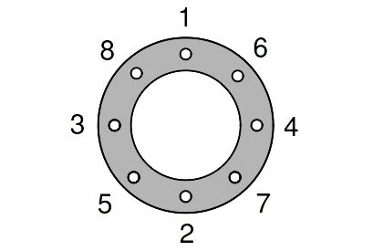
With one wrench, you would tighten each bolt to a preliminary torque in the sequence shown. Then, you would repeat the tightening sequence with additional torque for a more cycles until all bolts had been tightened to the recommended torque value. Note how the torque sequence alternates between four quadrants of the flange, ensuring the flanges are evenly compressed together as all bolts are gradually tightened. This technique of alternating quadrants around the circle is often referred to as cross-torquing.
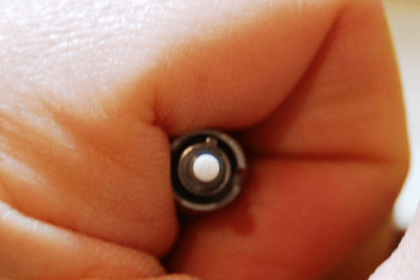
Special wrenches called torque wrenches exist for the purpose of measuring applied torque during the tightening process. In critical, high-pressure applications, the actual stretch of each flange bolt is measured as a direct indication of bolting force. A special bolt sold under the brand name of Rotabolt contains it own built-in strain indicator, letting the mechanic know when the bolt has been sufficiently tightened regardless of the tool used to tighten it.
Another important procedure to observe when working with flanged pipe connections is to loosen the bolts on the far side of the flange before loosening the bolts on the side of the flange nearest you. This is strictly a precautionary measure against the spraying of process fluid toward your face or body in the event of stored pressure inside of a flanged pipe. By reaching over the pipe to first loosen flange bolts on the far side, if any pressure happens to be inside the pipe, it should leak there first, venting the pressure in a direction away from you.
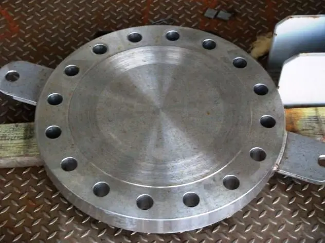
A special provision of flanged pipe connections is the ability to install a blank metal plate called a blind over or between flange faces, thereby preventing flow. This is useful when a pipe must be blocked in a semi-permanent fashion, for example if that section of pipe has been decommissioned, or if the section of pipe must be sealed for reasons of safety during maintenance operations.
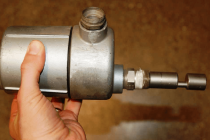
In order to install a blind, the flange joint must first be broken, then the flanges pried apart to provide the necessary space for the blind. After installing new gaskets along with the blind, the flanged bolts may then be re-installed and torqued to specification. A photograph of a stainless-steel blind (not installed on a pipe) appears here, two welded lifting tabs being clearly seen to facilitate handling this heavy piece of hardware:
In applications where “blinding” is frequent, a permanent form of blind called a spectacle blind may be installed to simplify the task. A spectacle blind is comprised of a regular blind plate attached to an equal-diameter ring by a short tab, the outline of which resembles a pair of spectacles:

Since the spectacle blind’s ring is exactly the same thickness as its blind plate, the piping system may be designed and built with the blind’s thickness in mind, the flange-to-flange gap remaining constant for the “open” and “blinded” states. This is especially helpful in very large piping systems, where the force required to separate formerly mated flange faces may be very large.
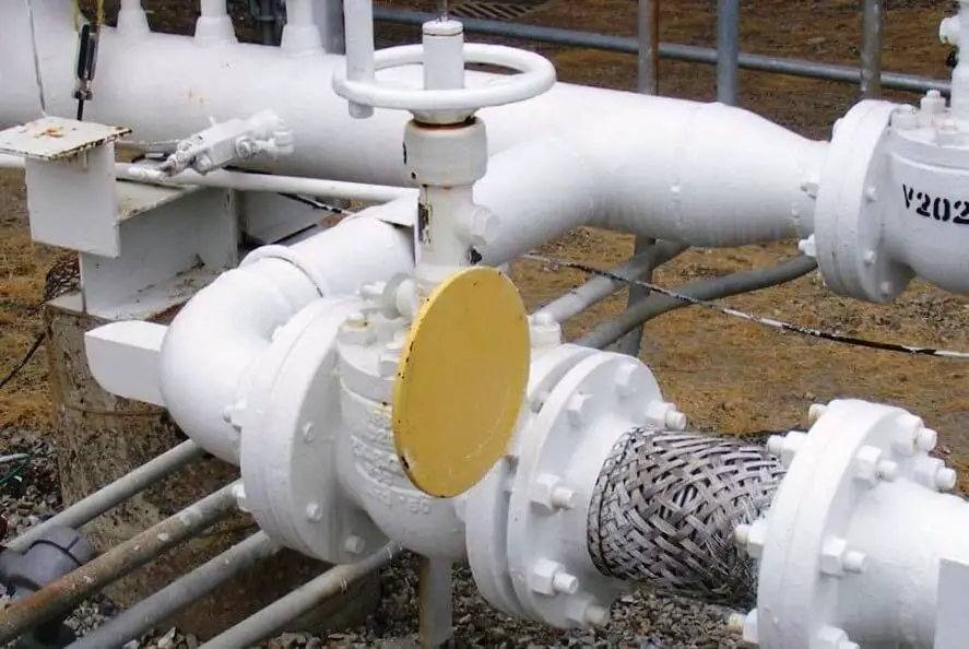
A spectacle blind may be seen in this next photograph, where the blind is installed in such a way that the yellow-painted “blind” half is exposed and the “open” half is sandwiched between the pipe flanges to allow flow through that pipe:
This next photograph shows a spectacle blind installed the other way, where the “open” half is exposed and the “blind” half is blocking any fluid from moving through the pipe: