Both gas and liquid control valves may experience what is generally known as choked flow. Simply put, “choked flow” is a condition where the rate of flow through a valve does not change substantially as downstream pressure is reduced.
Ideally, turbulent fluid flow rate through a control valve is a simple function of valve flow capacity (Cv) and differential pressure drop (P1 − P2), as described by the basic valve flow equation:

Where,
Q = Volumetric flow rate of liquid (gallons per minute, GPM)
Cv = Flow coefficient of valve
P1 = Upstream pressure of liquid (PSI)
P2 = Downstream pressure of liquid (PSI)
Gf = Specific gravity of liquid (ratio of liquid density to standard water density)
This equation simply does not apply for choked-flow conditions.
In a gas control valve, choking occurs when the velocity of the gas reaches the speed of sound for that gas. This is often referred to as critical or sonic flow. In a liquid control valve, choking occurs with the onset of flashing.
The reason sonic velocity is relevant to flow capacity for a control valve has to do with the propagation of pressure changes in fluids.
Pascal’s principle tells us that changes in pressure within a closed fluid system will manifest at all points in the fluid system, but this never happens instantaneously. Instead, pressure changes propagate through any fluid at the speed of sound within that fluid.
If a fluid stream happens to move at or above the speed of sound, pressure changes downstream are simply not able to overcome the stream’s velocity to affect anything upstream, which explains why the flow rate through a control valve experiencing sonic (critical) flow velocities does not change with changes in downstream pressure: those downstream pressure changes cannot propagate upstream against the fast-moving flow, and so will have no effect on the flow as it accelerates to sonic velocity at the point(s) of constriction.
Choked flow conditions become readily apparent if the flow-versus-pressure function of a control valve at any fixed opening value is graphed.
The basic valve flow equation predicts a perfectly straight line at constant slope with flow rate (Q) as the vertical variable and the square root of pressure drop (√(P1 − P2)) as the horizontal variable.
However, if we actually test a control valve by holding its upstream liquid pressure (P1) constant and varying its downstream pressure (P2) while maintaining a fixed stem position, we notice a point where flow reaches a maximum limit value:
Choked Flow of Control Valves
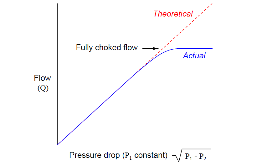
In a choked flow condition, further reductions in downstream pressure achieve no greater flow of liquid through the valve.
This is not to say that the valve has reached a maximum flow – we may still increase flow rate through a choked valve by increasing its upstream pressure. We simply cannot coax any more flow through a choked valve by decreasing its downstream pressure.
An approximate predictor of choked flow conditions for gas valve service is the upstream-to minimum absolute pressure ratio.
When the vena-contracta pressure is less than one-half the upstream pressure, both measured in absolute pressure units, choked flow is virtually guaranteed.
One should bear in mind that this is merely an approximation and not a precise prediction for choked flow. Much more information is needed about the valve design, the particular process gas, and other factors in order to reliably predict the presence of choking.
Choked flow in liquid services is predicted when the vena-contracta pressure equals the liquid’s vapor pressure, since choking is a function of flashing for liquid flow streams.
No attempt will be made in this book to explain sizing procedures for control valves in choked-flow service, due to the complexity of the subject.
An interesting and useful application of choked flow in gases is a device called a critical velocity nozzle. This is a nozzle designed to allow a fixed flow rate of gas through it given a known upstream pressure, and a downstream pressure that is sufficiently low to ensure sonic velocities in the nozzle throat.
One practical use for critical velocity nozzles is in the flow testing of compressed air systems. One or more of these nozzles are connected to the main header line of an air compressor system and allowed to vent to atmosphere.
So long as the compressor(s) are able to maintain constant header pressure, the flow rate of air through the nozzles(s) is guaranteed to be fixed, allowing a technician to monitor compressor parameters under precisely known load conditions.
