Inst ToolsInst ToolsInst Tools
  • Courses
  • Automation
    • PLC
    • Control System
    • Safety System
    • Communication
    • Fire & Gas System
  • Instrumentation
    • Design
    • Pressure
    • Temperature
    • Flow
    • Level
    • Vibration
    • Analyzer
    • Control Valve
    • Switch
    • Calibration
    • Erection & Commissioning
  • Interview
    • Instrumentation
    • Electrical
    • Electronics
    • Practical
  • Q&A
    • Instrumentation
    • Control System
    • Electrical
    • Electronics
    • Analog Electronics
    • Digital Electronics
    • Power Electronics
    • Microprocessor
Search
  • Books
  • Software
  • Projects
  • Process
  • Tools
  • Basics
  • Formula
  • Power Plant
  • Root Cause Analysis
  • Electrical Basics
  • Animation
  • Standards
  • 4-20 mA Course
  • Siemens PLC Course
Reading: Actuator Sensor Interface (ASi) Protocol in PLC
Share
Notification Show More
Font ResizerAa
Inst ToolsInst Tools
Font ResizerAa
  • Courses
  • Design
  • PLC
  • Interview
  • Control System
Search
  • Courses
  • Automation
    • PLC
    • Control System
    • Safety System
    • Communication
    • Fire & Gas System
  • Instrumentation
    • Design
    • Pressure
    • Temperature
    • Flow
    • Level
    • Vibration
    • Analyzer
    • Control Valve
    • Switch
    • Calibration
    • Erection & Commissioning
  • Interview
    • Instrumentation
    • Electrical
    • Electronics
    • Practical
  • Q&A
    • Instrumentation
    • Control System
    • Electrical
    • Electronics
    • Analog Electronics
    • Digital Electronics
    • Power Electronics
    • Microprocessor
Follow US
All rights reserved. Reproduction in whole or in part without written permission is prohibited.
Inst Tools > Blog > Communication > Actuator Sensor Interface (ASi) Protocol in PLC

Actuator Sensor Interface (ASi) Protocol in PLC

In this post, we will understand the use of the Actuator Sensor Interface (ASi) protocol in the programmable logic controller (PLC).

Last updated: October 17, 2023 2:01 pm
Viral Nagda
Communication PLC Tutorials
1 Comment
Share
7 Min Read
SHARE

In this post, we will understand the use of the Actuator Sensor Interface (ASi) protocol in the programmable logic controller (PLC).

Contents
ASi ProtocolActuator Sensor Interface in PLCMaster ModuleSlave ModulesPower SupplyInterface SystemConclusion

Earlier, in PLCs, there was only a provision for direct connection of sensors and actuators (field devices) to it via its corresponding hardwiring.

So, as the number of IO’s increases, the hardwiring also increases and indirectly increases the complexity of the system. To overcome this disadvantage, a protocol named actuator sensor interface (ASi) was developed.

ASi Protocol

The ASi protocol is a simple interface system for connecting sensors and actuators with only two wires. It has very high-speed communication, very reliable, and has high levels of noise immunity to make it useful for a large variety of field device connections. It is very cost-effective due to a large-scale reduction in wiring and complexity.

What makes it simple is a single unshielded two wire conductor cable; that makes the overall electrical design constraints simple and easy to manage.

ASi protocol works in master-slave format. It consists of an ASi master module that can communicate with up to 62 slave IO modules.

Each slave device supports up to eight inputs and eight outputs at a time simultaneously. So, a total of 992 IO’s (496 inputs and 496 outputs) can be handled properly by the master module.

The scan time of the IO’s is very fast in this protocol. In fact, it is even faster than the standard IO scanning that is done in PLC. It works similarly to the Modbus protocol in terms of polling activity.

Each slave device is polled for a certain time. If the master does not receive any response from the slave, it will move ahead to the next slave; and it is continuously sharing the diagnostics and status of the slaves with the PLC.

A network of 32 devices can provide a scan rate of 5ms per IO point. If you go higher to 62 devices, it will become a little slow and provide a scan rate of 10ms per IO point.

Actuator Sensor Interface in PLC

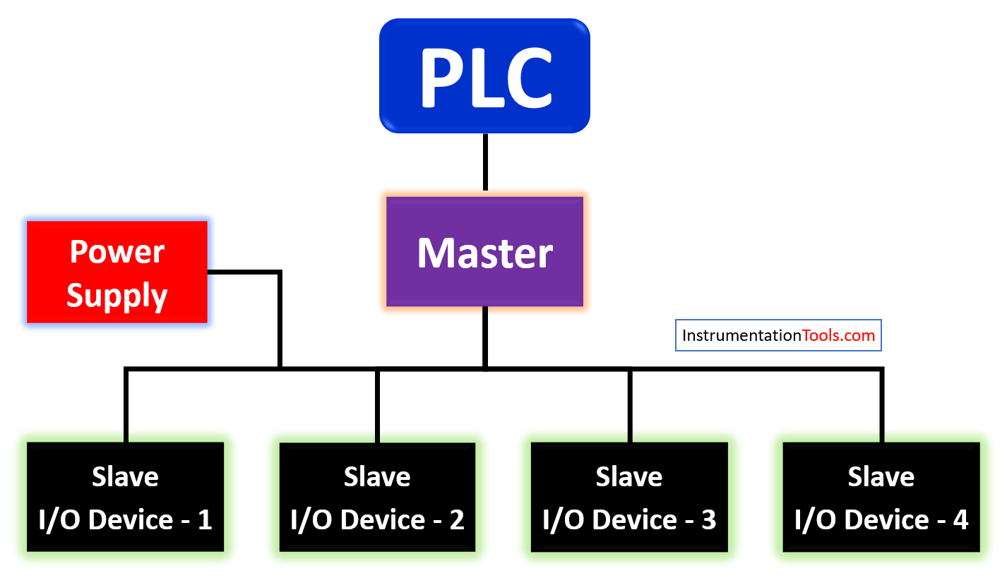
Refer to the below image, which is the system architecture of an ASi protocol layout.

It consists of four main components.

They are

  1. Master module,
  2. Slave module,
  3. Power supply, and
  4. Interface cables.
Actuator Sensor Interface (ASi) Protocol in PLC

Master Module

The master module is the main component that communicates the data to PLC on any Fieldbus network (Ethernet or Modbus layer).

It organizes data flow to and from the slaves in a controlled and cyclic manner to the PLC and maintains all the troubleshooting data recorded from the slaves; for transferring it to the PLC.

Slave Modules

The slave modules are the actual modules where the IO’s are connected. Each slave device is identified by a device ID.

The slave has connections for inputs and outputs as discussed earlier.

Power Supply

The power supply is the heart of the system which provides power to the whole ASi network. It provides a constant 30V voltage to the line for master and slave devices.

The main function of this module that separates it from other power supplies is that it transmits power on the same line in which data is flowing.

So, it decouples power from data and isolates it properly (As there are only two wires in a cable required as discussed; power and data).

There are also ASi modules available that work in 24V supply. In that case, a separate power supply module will not be required. The bus will consume power from the PLC rack system directly.

Interface System

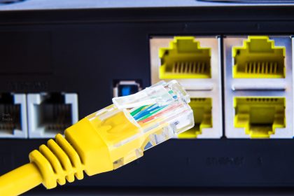
Coming to the main thing that is special about this protocol; is the cable interface system. Normally, two standard cables are used in this system.

One is a yellow cable carrying data and power; the other is a black cable carrying 24V to actuators. Only two wires in a single cable carry both the power and data.

A special piercing technology (mechanically keyed cable with connector) makes the connection safe and easy to use.

Due to the mechanical pin key connection, there is no chance of loose wiring or reverse polarity; as only the corresponding, pin will fit inside the connector. It is the same as a cable connected to a TV setup box; where you see a connector at the setup box end to make the connection. All this makes the connection reliable and free of complexity, as the number of wires is reduced compared to traditional IO wiring in PLC.

The maximum distance between the devices is 100 m. You can extend the connection via use of repeaters or extension modules.

Conclusion

Thus, it can be seen that the ASi protocol is a largely useful protocol for IO handling in today’s times of large networks. They reduce wiring to a very large extent and also the complexity of the system.

If you liked this article, then please subscribe to our YouTube Channel for Instrumentation, Electrical, PLC, and SCADA video tutorials.

You can also follow us on Facebook and Twitter to receive daily updates.

Read Next:

  • Digital Outputs in PLC
  • Servo Motor Drives
  • Fieldbus versus 4-20 mA
  • Input-Output Modules
  • What is a Motion Controller?
Don't Miss Our Updates
Be the first to get exclusive content straight to your email.
We promise not to spam you. You can unsubscribe at any time.
Invalid email address
You've successfully subscribed !

Continue Reading

Introduction to SCADA
Using Clock Memory Bits in TIA Portal – Siemens PLC
WirelessHART device Configuration
Create a Function (FC) for a Valve Logic in Siemens PLC
Difference between Signal Cables and Control Cables
Difference between PLC and HMI
Share This Article
Facebook Whatsapp Whatsapp LinkedIn Copy Link
Share
1 Comment
  • Mario Danilovic says:
    November 20, 2021 at 12:00 pm

    Where is have book of ASi communications (pdf) ? Explained in detail.

    Thanks you

    Reply

Leave a Reply Cancel reply

Your email address will not be published. Required fields are marked *

Stay Connected

128.3kFollowersLike
69.1kFollowersFollow
208kSubscribersSubscribe
38kFollowersFollow

Categories

Explore More

GET Command – Siemens PLC-to-PLC Communication Project
PLC Analog Input Conversion Formula
How to Convert Current to Voltage using Resistor ?
WirelessHART Network Gateway Device
What are Faceplates? How to Create a Faceplate? HMI Visualization
Split Range Control Application using PLC Ladder Logic
Sequential Operation of Output Bits using Two Push buttons
How to Delete the Siemens CPU Memory?

Keep Learning

PLC Programming Projects for Beginners

PLC Programming Projects for Beginners

What is Timeout in Communication Protocols

What is Timeout in Communication Protocols?

Difference Between Industrial Computer and Normal Computer

Difference Between Industrial Computer (IPC) and Normal Computer (PC)

Anti-static Wrist Straps

Anti-static Wrist Straps in Industrial Automation

PLC Raw Count Calculation formula for Pressure Transmitter

PLC Raw Count Calculation for Pressure Transmitter

Yokogawa DCS CPU

System Cabinet Health Checks – PLC and DCS Industrial Automation

Sorting Defective Parts PLC Logic

Advanced PLC Programming for Defective Parts Sorting

PLC Tutorials - Timers and Counters

Difference between Timer and Counter – PLC Basics

Learn More

OPC Communication Interview Questions Answers

OPC Communication Interview Questions and Answers

How to Install a Rotameter

How to Install a Rotameter

dead-weight-tester-principle

What is a Dead Weight Tester?

Definitions of Electrical Grounding

Definitions of Electrical Grounding

Process Pressure Measurement Objective Questions

Process Pressure Measurement Objective Questions

Strain Gauge Pressure Sensor Principle

Strain Gauge Pressure Sensor Principle

Mechanical Engineering Plant Problems Solved

Mechanical Engineering Plant Problems Solved – Root Cause Analysis

Current Divider Rule

Current Divider Rule

Follow US
All rights reserved. Reproduction in whole or in part without written permission is prohibited.
Welcome Back!

Sign in to your account

Username or Email Address
Password

Lost your password?