Inst ToolsInst ToolsInst Tools
  • Ask
  • Courses
  • Videos
  • Q & A
    • Interview
      • Instrumentation
      • Electronics
      • Electrical
      • Practical Questions
    • MCQ
      • Instrumentation MCQ
      • Electrical MCQ
      • Electronics MCQ
      • Control Systems MCQ
      • Analog Electronics MCQ
      • Digital Electronics MCQ
      • Power Electronics MCQ
      • Microprocessor MCQ
      • Multiple Choice Questions
  • EE
    • Electronics
      • Electronics Q & A
      • Electronic Basics
      • Electronic Devices & Circuits
      • Electronics Animation
      • Digital Electronics
    • Electrical
      • Electrical Basics
      • Electrical Q & A
      • Power Electronics
      • Electrical Machines
      • Electrical Animation
      • Power Systems
      • Switchgear & Protection
      • Transmission & Distribution
  • Measure
    • Control Valves
    • Calibration
    • Temperature
    • Pressure
    • Flow
    • Level
    • Analyzers
    • Switches
    • Vibration
    • Solenoid Valve
  • Control
    • PLC Tutorials
    • Control Systems
    • Safety Instrumented System (SIS)
    • Communication
    • Fire & Gas System
  • More
    • Design
    • Tools
    • Animation
    • Basics
    • Formulas
    • Standards
    • TextBooks
    • Common
    • Software
    • Excel Tools
    • Erection & Commissioning
    • Process Fundamentals
    • Videos
    • Books
Search
All rights reserved. Reproduction in whole or in part without written permission is prohibited.
Reading: Automation Panel Electronic Cards Failure investigation
Share
Notification Show More
Font ResizerAa
Inst ToolsInst Tools
Font ResizerAa
  • Courses
  • PLC Tutorials
  • Control Systems
Search
  • Ask
  • Courses
  • Videos
  • Q & A
    • Interview
    • MCQ
  • EE
    • Electronics
    • Electrical
  • Measure
    • Control Valves
    • Calibration
    • Temperature
    • Pressure
    • Flow
    • Level
    • Analyzers
    • Switches
    • Vibration
    • Solenoid Valve
  • Control
    • PLC Tutorials
    • Control Systems
    • Safety Instrumented System (SIS)
    • Communication
    • Fire & Gas System
  • More
    • Design
    • Tools
    • Animation
    • Basics
    • Formulas
    • Standards
    • TextBooks
    • Common
    • Software
    • Excel Tools
    • Erection & Commissioning
    • Process Fundamentals
    • Videos
    • Books
Follow US
All rights reserved. Reproduction in whole or in part without written permission is prohibited.
Inst Tools > Blog > Root Cause Analysis (RCA) > Automation Panel Electronic Cards Failure investigation

Automation Panel Electronic Cards Failure investigation

Discover the causes and solutions for electronic card failures in automation panels. Learn how to prevent damage to instrument systems.

Last updated: September 25, 2024 12:27 pm
vicky
Root Cause Analysis (RCA)
No Comments
Share
6 Min Read
SHARE

Learning from an incident in which frequent card failure occurred in a panel.

Contents
Automation Panel Electronic Cards FailureRoot Cause AnalysisSolutionVortex CoolerAdvantages of Vortex CoolerConclusion

Panels are one of the important parts of the instrument systems. Most of the system components, i.e. PLC cards, power supply cards, barriers, and many more, are installed inside the panel. This panel can be in the panel room which is also called the rack room and this panel can be in the field also.

The panel room or rack room is usually a place where temperature and humidity are regulated so that the instrument system in the panel room does not get damaged. But the surrounding environment in the field can be good and sometimes too harsh.

Let us see one incident related to this.

Automation Panel Electronic Cards Failure

Background of the incident:

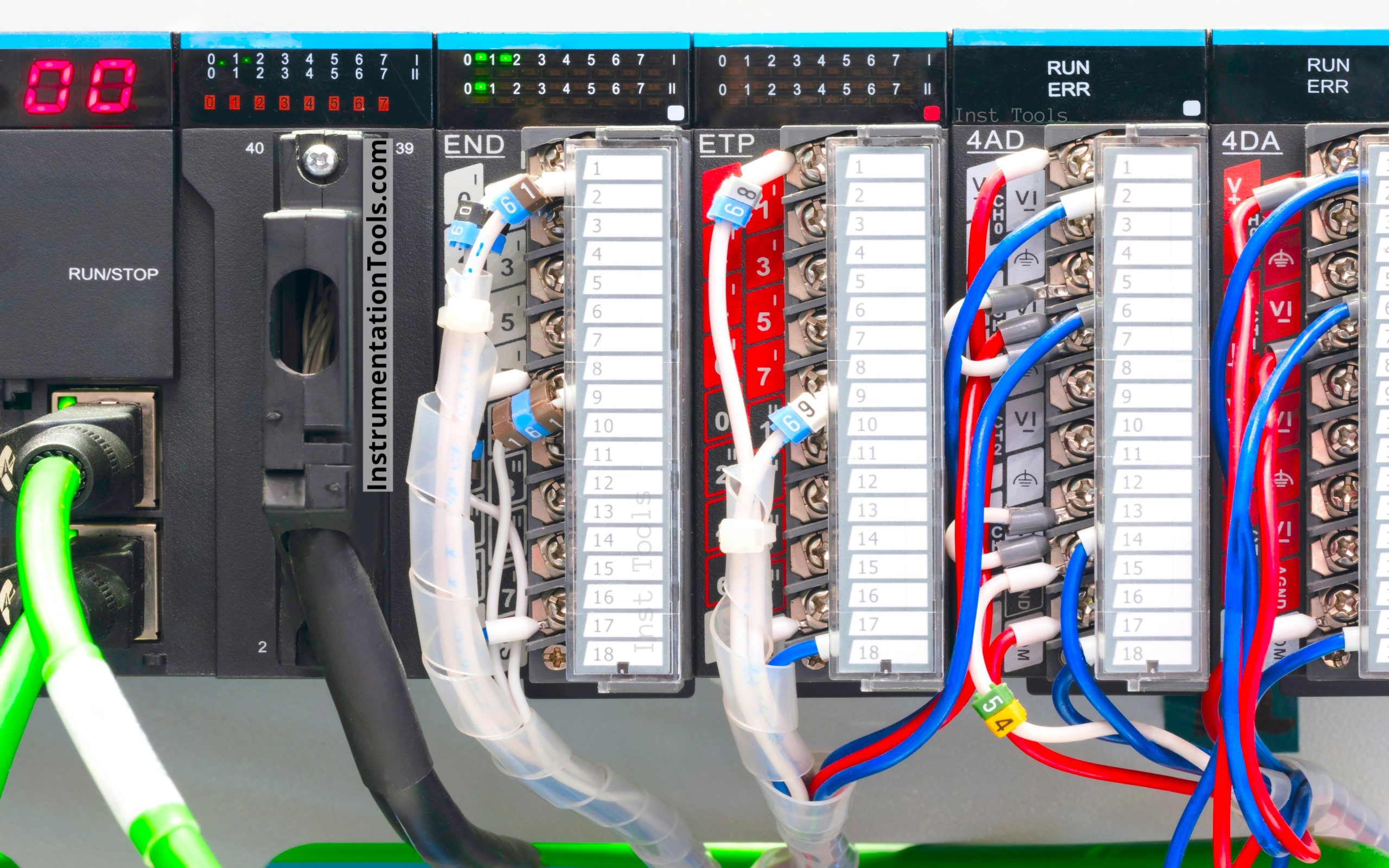
A panel having a controller and some cards for running a small plant was installed in the field area. A total of 9 cards, 32 barriers, and 3 relays were installed in this panel.

Card Failures in Automation Panels

The temperature of the surroundings is in between 10 degrees Celsius (minimum temperature in the month of December-January) and 35 degrees Celsius (maximum temperature in the month of May-June) during the year. The panel was installed 2 years ago in September month and Instrument Engineers were facing frequent issues of barrier failure in this panel after 9 months i.e. in May month of next year. After a year, the problem of card failure also started.

So, Instrument engineers studied this and came up with a very cost-effective solution. This solution not only saved them from frequent failure of components but also increased the uptime of the plant.

Root Cause Analysis

So, how did the Instrument Engineers come to a solution and what was it?

When the Instrument Engineers started discussing about this problem and a permanent solution to this problem, the Instrument Engineers first doubted the quality of all these failed barriers and cards. However, the Instrument Engineers realized that the quality of these failed barriers and cards cannot be doubted because barriers and cards of a similar lot are installed in other panels and also in different areas.

Now the Instrument Engineers thought that there might be moisture inside the panel which could be causing this problem. So, the panel was thoroughly checked for traces of moisture, but this was also not the problem. The panel was tightly locked and silastic was used on the openings to protect it. Cable glands were perfect and blind plugs in spare cable entry holes were also perfect. Then the Instrument Engineers thought of excessive heat inside the panel which may have damaged these barriers and cards.

So, to verify this, the Instrument Engineers did the thermography and found that many places inside this panel had hotspots of 43 degrees Celsius when the surrounding environmental temperature was just 20 degrees Celsius. Now, imagine the inside temperature when the surrounding environmental temperature reaches 35 degrees Celsius. This will definitely cause damage to the components installed inside the panel.

Solution

The Instrument Engineers installed a vortex cooler for this panel whose approximate cost was around 18,000 Rs. After running the vortex cooler for a few hours, the hotspot of 43 degrees Celsius had become 24 degrees Celsius (in the same surrounding environmental conditions). This vortex cooler gave a huge financial benefit because the component failure frequency was reduced very much which increased plant uptime also.

Some of you might be thinking what is vortex cooler?

Let us have a quick look at a vortex cooler.

Vortex Cooler

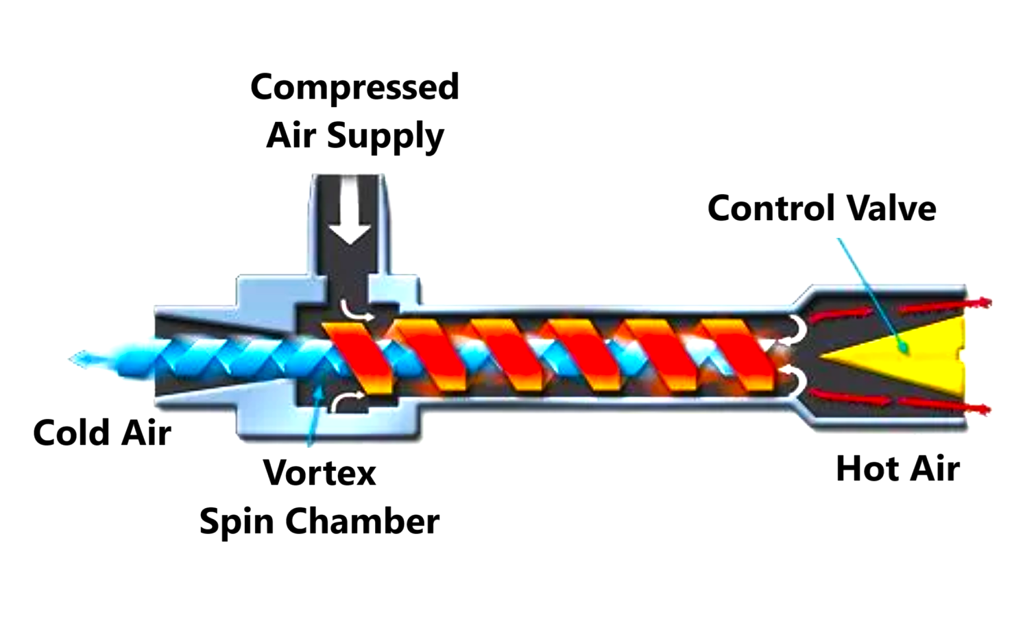
Explaining how does a vortex cooler works is a bit difficult, still in an easy language a vortex cooler can be compared to a heat exchanger. Compressed air is given as an input to the vortex cooler from one side. From one end hot air comes out and from the opposite end cold air comes out.

The compressed air travels to the hot end side in the form of vortices having very high RPM where an adjustable valve is present. Some air goes out from there and other comes back from inside of these vortices and travel to the opposite side i.e. cold side. Here this air becomes cold by exchanging energy. The below figure shows a vortex cooler.

vortex cooler
Image Courtesy: Exair

Advantages of Vortex Cooler

The benefits of vortex cooler are:

  1. The vortex cooler has no moving parts
  2. Only compressed air with normal temperature (20 degrees Celsius to 30 degrees Celsius) is needed
  3. No power supply is needed
  4. Maintenance free design

Conclusion

A few important things we learned from this case are:

  1. If there are any barriers or cards, then air conditioning is needed
  2. Regular LLF of every instrument item is needed whether it is a transmitter or gauge or cable or panel
  3. Regular thermography of components installed in panels should be done
  4. Regular cleaning of components installed in panels should be done

Read Next:

  • Process Air Compressor Overhauls
  • Refrigeration Compressor Turbine
  • Erratic Stroking of Control Valves
  • Temperature Sensors Fault Problem
  • Junction Box Corrosion Problem
Don't Miss Our Updates
Be the first to get exclusive content straight to your email.
We promise not to spam you. You can unsubscribe at any time.
Invalid email address
You've successfully subscribed !
Target Flow Transmitters Failed the Very Midnight
Flanged Rotameter Caused Pipe Weld Cracks and Gives Wrong Readings
Fan Motor Frequent Journal Bearing Failures Posed Plant Outages
Lessons Learned from Actuator Passing Incidents
Thermowell Shank to Flange Repeat Weld Leaks
Share This Article
Facebook Whatsapp Whatsapp LinkedIn Copy Link
Share
Leave a Comment

Leave a Reply Cancel reply

Your email address will not be published. Required fields are marked *

Stay Connected

128.3kFollowersLike
69.1kFollowersFollow
208kSubscribersSubscribe
38kFollowersFollow

Categories

Recent Comments

  • Kamli on Top Free PLC Software
  • Guifty Shimica on Top Non-PLC Certification Courses for Automation Professionals
  • Guifty Shimica on Top Non-PLC Certification Courses for Automation Professionals
  • MIHARITSOA Aina Sitraka on Top Non-PLC Certification Courses for Automation Professionals

Related Articles

Bently Nevada Proximity Probe

Root Cause Analysis for Vibration Probe Not Responding

Compressor Cracked Shaft Spacers

Compressor Cracked Shaft Spacers

Lightning Arrester Bursts Problem

Frequent Feeder-A Lightning Arrester (LA) Bursts – Root Cause Analysis

Solving Critical Control Valve Hunting

Solving Control Valve Hunting: Instrument Troubleshooting

Solenoid Valve Failure in Plant Start-Up

Solenoid Valve Failure in Plant Start-Up: Identifying the Root Cause

Under and Over-Capacity Control Valve

Under and Over-Capacity Control Valve Pose Poor Controllability

Temperature Sensors Fault

18 Temperature Sensors Fault Leads to Plant Shutdown

Erratic Radar Level Gauges

Erratic Radar Level Gauges Delays a Refinery Commissioning

More Articles

Electrical Machines Questions and Answers

Armature Winding Questions

Moving Iron Vane Meter Movement

Moving Iron Vane Meter Movement

Level Loop Troubleshooting

Identify Faults in PID Control Loop

CPU Communication Ports in Siemens PLC

Types of CPU Communication Ports in Siemens PLC

RJ45 Connector Pins

How to make RJ45 cable

Level Control Loop Principle

Integrating Processes – Liquid Level Control

Chromatography Questions & Answers

Gas Solid Chromatography Questions & Answers

wash column temperature control

Pneumatic Instrumentation

Follow US
All rights reserved. Reproduction in whole or in part without written permission is prohibited.
Welcome Back!

Sign in to your account

Username or Email Address
Password

Lost your password?