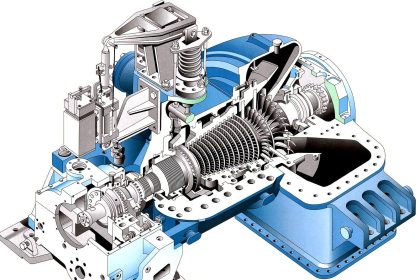
The turbo alternator is a continuously running machine.
Components like main bearings, thrust bearings, and reduction gears may get heated up due to turning friction during run time.
Hence a full-fledged lubrication system is required for the turbo alternators. Also, the lubrication system helps to cool journals and bearing surfaces.
The lubrication oil is required to flow continuously with controlled pressure and temperature.
Oil must be free from injurious foreign matter.
Lubrication System
A block diagram of a lubrication system for a turbo alternator is shown below
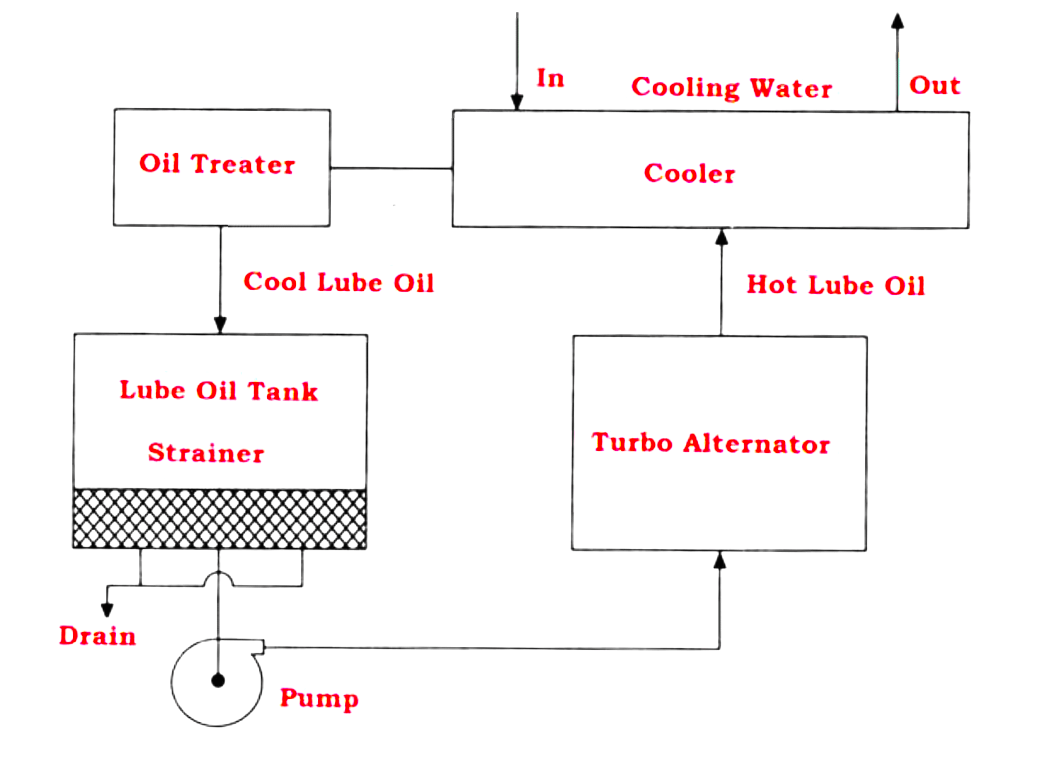
- The main lube oil tank is installed at an elevated plane.
- The system consists of a centrifugal pump attached to the turbine shaft, the jet pump creates enough pressure.
- A distribution box is added to divert lubrication oil to different sections of the turbine alternator.
- An oil strainer and oil treater are used to maintain the purity of the oil.
- Some portion of lubrication oil from the overhead tank is drained periodically to avoid contamination due to sludge formation.
- The oil cooler is used to reduce the temperature of the oil coming out from the turbine lubrication system and is recirculated.
Controls in Lubrication System
Three control loops are required to ensure proper lubrication to different sections of the Turbo Alternator.
- Lube oil pressure loop or flow rate in the line.
- Lube oil temperature loop from the main tank to the piping system.
- Lube oil main tank level to ensure availability of enough oil quantity.
Control of Lube Oil Pressure or Flow
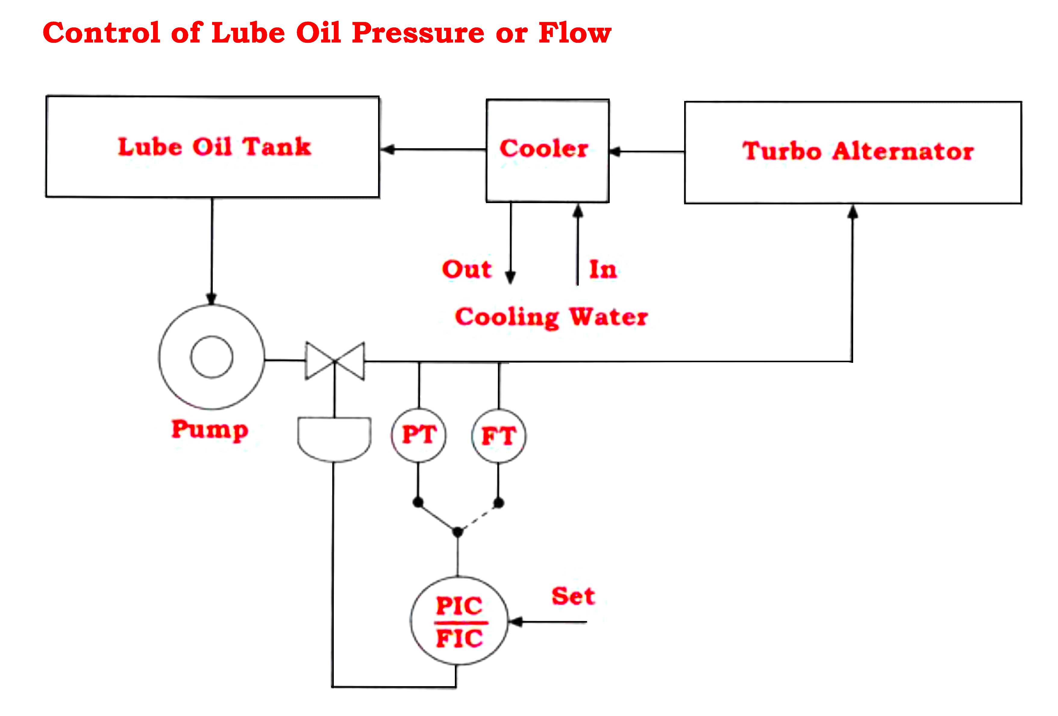
- To ensure lubrication oil circulation in the system, either pressure or the flow rate must be controlled automatically.
- Measurement of both pressure & flow rate is possible, but only one is used for controlling.
- The other one can be used for indication and recording.
- It makes the operator get an idea about system performance.
Lube Oil Temperature Control
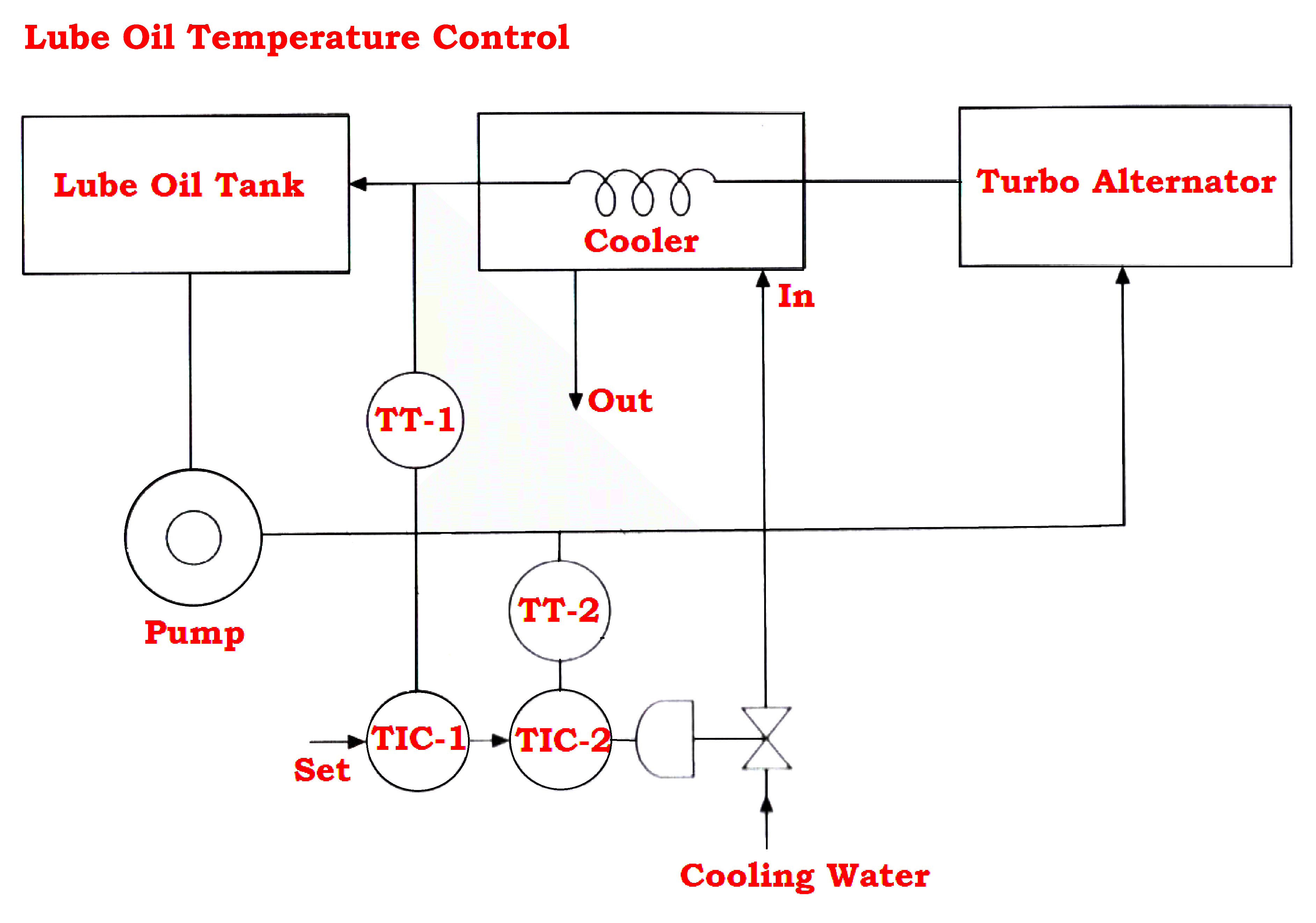
- The lubrication oil gets heated up and exchanges heat energy when it passes through bearings and gears.
- The oil is required to recirculate to cool it to normal temperature.
- The figure shows a cascade control system with a cooler outlet temperature as the master loop and the lube oil tank outlet temperature as the slave loop.
- Generally, ordinary water is used as a cooling medium at room temperature after cooling this water is drained out.
- Refrigerated water or any other liquid can also be used for effective cooling.
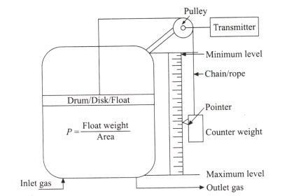
Lube Oil Tank Level Control
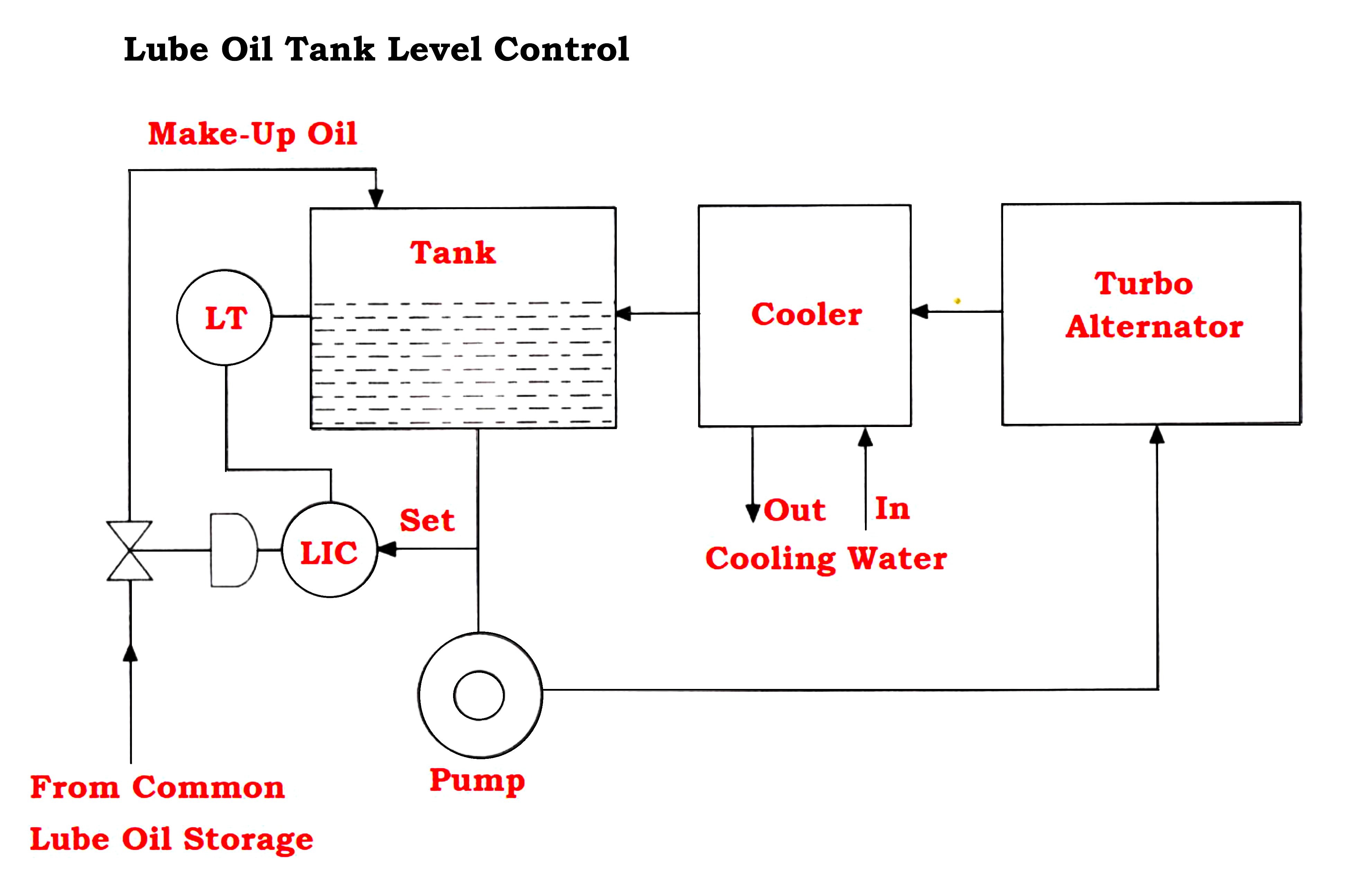
- In a lube oil circulation system, we may face some loss of lube oil.
- To avoid this loss of lube oil, an automatic lube oil tank level control system is done.
- The above diagram shows an automatic lube oil tank level control system.
Turbo-Alternator Cooling System
Basically, in all power plants, we find these three cooling systems in the turbo-alternator process
Lube Oil Cooling System
- Lube oil is used to cool thrust and collar bearings, gears, and surfaces of bearings.
- The heat-exchanged lube oil is cooled again for further re-circulation
Condensate Cooling System
- Here the exhausted steam from the low-pressure side of the turbine is condensed into feed water for the recirculation circuit.
- For this purpose, a huge amount of cooling water is required and is taken from the river or pond.
- But, this water is not treated like boiler-feed water in WTP.
- After circulating through the condenser, this water is pumped to the cooling tower for further recirculation.
- Generally, we do not require any automatic control for this process.
Alternator or Generator Cooling System
- The electrical loss in the generator is converted into heat and raises the winding temperature, insulation, and machine parts.
- Eddy current and Hysteresis losses are generated in the iron core.
- A copper loss is generated in the windings called electrical loss.
- If the heat generated by windings is not eliminated, the machine gets overheated and the insulation gets damaged it becomes weak and the windings get overheated and burnt out.
- Hence it is essential for continuous cooling of the generator during runtime.
Generally, there are three methods of cooling.
Open Air Cooling System
- This open-air cooling system uses atmospheric air as cooling media.
- This method is employed for low-capacity generators of normally up to 3 MW. The fresh air from the atmosphere is forced to cool the rotating and stationary components.
- As there is a possibility of dust and impurities entering the machine and affecting its performance of the machine.
Closed Air Cooling System
- This Closed air cooling system is normally employed in large generators with a capacity of up to 100 MW.
- The air is circulated for cooling.
- The hot air coming out is cooled back in a heat exchanger with a water cooling system.
- This is again re-circulated for cooling the generator.
- This method is costly, but the possibility of dust and impurities entering the machine is less compared to an open-air cooling system.
Hydrogen Cooling System
- A hydrogen cooling system is used for generators of a capacity of more than 100 MW or more.
- The thermal properties of hydrogen such as specific heat and thermal conductivity are best compared to air.
- This allows reduced windage and better cooling operation.
- Due to the low density of hydrogen, the windage and ventilating loss is low.
Advantages of Hydrogen Cooling
- The cooling system is neat and clean.
- Low noise due to lighter cooling.
- Requires less active materials like iron and copper than air-cooled generators.
- Increases generator efficiency.
- The warm exiting hydrogen can be cooled in a heat exchanger with cooling water and recirculated.
Disadvantages of Hydrogen Cooling
- The system is Costly.
- Highly explosive when hydrogen mixes with air in a certain proportion.
- Requires special maintenance tools and trained staff.
- As hydrogen is used about a pressure of 2 bar since the generator must be gas tightened with special seals.
- Forced hydrogen cooling is used for larger units of above 500 MW.
- Generally, Hydrogen filling is done when the generator is flushed with liquid carbon dioxide to avoid explosion.
If you liked this article, then please subscribe to our YouTube Channel for Electrical, Electronics, Instrumentation, PLC, and SCADA video tutorials.
You can also follow us on Facebook and Twitter to receive daily updates.
Read Next:
- Electrostatic Precipitator
- Steam Circuits in Power Plants
- Furnace Draft Control System
- Turbine Steam Pressure Control
- Proportional and Servo Valves