Inst ToolsInst ToolsInst Tools
  • Courses
  • Automation
    • PLC
    • Control System
    • Safety System
    • Communication
    • Fire & Gas System
  • Instrumentation
    • Design
    • Pressure
    • Temperature
    • Flow
    • Level
    • Vibration
    • Analyzer
    • Control Valve
    • Switch
    • Calibration
    • Standards
    • Basics
    • Formula
    • Erection & Commissioning
    • Process Fundamentals
    • Root Cause Analysis
  • Interview
    • Instrumentation
    • Electrical
    • Electronics
    • Practical
  • Q&A
    • Instrumentation
    • Control System
    • Electrical
    • Electronics
    • Analog Electronics
    • Digital Electronics
    • Power Electronics
    • Microprocessor
Search
All rights reserved. Reproduction in whole or in part without written permission is prohibited.
Reading: Motor Cooling Methods
Share
Notification Show More
Font ResizerAa
Inst ToolsInst Tools
Font ResizerAa
  • Courses
  • PLC
  • Control Systems
Search
  • Courses
  • Automation
    • PLC
    • Control System
    • Safety System
    • Communication
    • Fire & Gas System
  • Instrumentation
    • Design
    • Pressure
    • Temperature
    • Flow
    • Level
    • Vibration
    • Analyzer
    • Control Valve
    • Switch
    • Calibration
    • Standards
    • Basics
    • Formula
    • Erection & Commissioning
    • Process Fundamentals
    • Root Cause Analysis
  • Interview
    • Instrumentation
    • Electrical
    • Electronics
    • Practical
  • Q&A
    • Instrumentation
    • Control System
    • Electrical
    • Electronics
    • Analog Electronics
    • Digital Electronics
    • Power Electronics
    • Microprocessor
Follow US
All rights reserved. Reproduction in whole or in part without written permission is prohibited.
Inst Tools > Blog > Electrical Basics > Motor Cooling Methods

Motor Cooling Methods

There are a couple of methods used for selecting an electrical motor that will be adequately cooled during operation.

Last updated: November 4, 2022 2:51 pm
Viral Nagda
Electrical Basics
No Comments
Share
5 Min Read
SHARE

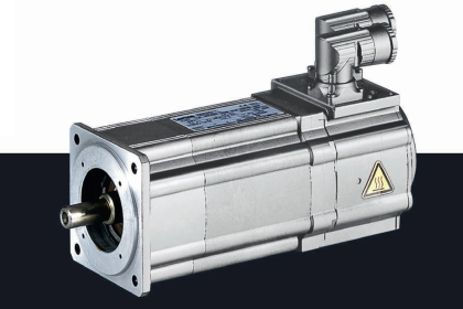
In this post, we will learn the various methods of cooling a motor.

Contents
Motor Cooling MethodsSelecting a MotorMotor Sizing with Service FactorHigh Motor Horsepower

Whenever an electrical current is passed through an electrical motor there is a buildup of heat. The amount of heat produced is a function of the work, or loading, done by the motor; the type of electrical signal being sent to the motor; and the eventual changes due to bearing wear and friction.

Whenever AC drives are used to control motors it means that the speed of the motor is going to be changed. And, depending upon motor loading, special attention needs to be given to how the motor is going to be cooled.

Motor Cooling Methods

Motor Cooling Methods

Generally speaking, less speed means less cooling. Different motor cooling designs are available.

Let us have a look at some of them:

  • Many motors are sized for a particular application, or horsepower rating, so that the heat produced from the current can be accepted and dissipated by the metal content of the motor. Normal convection and radiation dissipate the heat with the aid on an internal mixing fan. These motors are classified as “open drip-proof” or “totally enclosed nonventilated (TENV).”
  • Other electric motors incorporate a fan blade that rotates at the same speed as the motor shaft. This fan blows air across the outside of the motor, cooling it as it runs. However, if an AC drive is used, the lower in speed the motor is made to run, the slower the cooling fan will run also. This can result in a buildup of heat in the motor. These motors are called “totally enclosed fan-cooled (TEFC).”
  • Some types of motors use elaborate means for cooling. These are called “totally enclosed water-to-air cooled,” “totally enclosed air over,” and “totally enclosed unit cooled.” Obviously, the more complex the cooling method, the more expensive theactual motor will be.
  • Another method used is air pipe/tube cooling. In this technique, cooling pipes are formed around motor lamination and a fan is installed at the shaft. The heat generated at the rotor and stator is transferred to the cooling pipes through the fan. Another fan at the non-drive end drives the outside atmospheric air to the cooling pipes. This results in heat exchange, which cools the air and eventually, the motor.
  •  In the last method, there are high chances of dust and dirt accumulating in the motor side, apart from just cooling. So, to prevent this, one more advanced method is used called an air-to-air heat exchanger. In this technique, dust and dirt are prevented from entering the motor parts, as the whole enclosure is covered in a heat exchanger-type enclosure. It is completely similar to the AHU that we use for cooling enclosed rooms.

Selecting a Motor

There are a couple of different strategies used for selecting a motor that will be adequately cooled during operation:

Motor Sizing with Service Factor

One approach is to size the motor with a service factor. A service factor of 1.15 means that the motor has 15% more capacity when operating conditions are normal for voltage, frequency, and ambient temperature.

This 15% extra capacity means that the motor is built and sized when the duty cycle is severe, or the loading and speed range is moderate.

High Motor Horsepower

Another strategy is to simply go up in horsepower, which is how motors are sized. This might put a motor into a larger frame designation, thereby making it weigh more and allowing it to handle a greater amount of heat.

The concern with both of these strategies is that you could end up with a motor that is well oversized for the application. This would cause wasted energy and increase the cost of the motor. Another answer might be to add auxiliary cooling equipment to the motor.

In this way, we understand some general motor cooling methods.

If you liked this article, then please subscribe to our YouTube Channel for Electrical, Electronics, Instrumentation, PLC, and SCADA video tutorials.

You can also follow us on Facebook and Twitter to receive daily updates.

Read Next:

  • Applications of VFD
  • What is a Submersible Pump?
  • What is a Lightning Arrester?
  • What is a Power Transformer?
  • Motor Control in Control System
Don't Miss Our Updates
Be the first to get exclusive content straight to your email.
We promise not to spam you. You can unsubscribe at any time.
Invalid email address
You've successfully subscribed !

Continue Reading

NO vs NC Contact
Totally Enclosed Fan Cooled (TEFC) Motors Rampant Winding Burnouts
Types of Industrial Storage Batteries
VFD Simulator Download – Free Yaskawa V1000 Software
Variable Motor Speed Control
Motor Control Center – Purpose, Classification, and Advantages
Share This Article
Facebook Whatsapp Whatsapp LinkedIn Copy Link
Share
Leave a Comment

Leave a Reply Cancel reply

Your email address will not be published. Required fields are marked *

Stay Connected

128.3kFollowersLike
69.1kFollowersFollow
208kSubscribersSubscribe
38kFollowersFollow

Categories

Explore More

Difference Between Power Cable and Instrument Cable
Types of Relays used in an Air Circuit Breaker (ACB)
What is Floating Neutral? – Electrical Engineering Basics
Basics of Electricity Rates
De-energized Electrical Circuits, Networks, and Equipment
Lightning Arrester Basics and Terminology
Why is HV Testing important in Electrical Panels?
Testing of Thermal Protection Relay for Motors

Keep Learning

Why is IGBT used in VFD

Why is IGBT used in VFD?

Garage Door Roller Shutter

Shutter Door Control using Motor and Limit Switches

What is Switchgear and Electrical Substation?

What is Switchgear and Electrical Substation?

Residual Current Circuit Breaker (RCCB)

Residual Current Circuit Breaker (RCCB)

What are HP and LP Switches in HVAC

What are HP and LP Switches in HVAC?

What is an ELV System - Extra Low Voltage

What is an ELV System? – Extra Low Voltage

Allen-Bradley VFD

Motor VFD Drive features

Electrical Link Box

What is a Link Box?

Learn More

Vortex Flow Meter Principle

Vortex Flow meter Animation

Tank Gauging Measurement

Purpose of Tank Gauging Level Measurement

Closed Tank Liquid Level Measurement using Pressure Transmitter

Inferential Measurement based on Pressure

HART Communication

HART Communication Protocol Overview

Power Electronics Objective Questions

Thyristor Protection Objective Questions and Answers

current division Formula for Resistor Circuit

Current Division

Instrumentation Engineering Materials Test

Instrumentation Engineering Materials Test

Switchgear & Protection Objective Questions and Answers

Switchgear & Protection Objective Questions and Answers

Follow US
All rights reserved. Reproduction in whole or in part without written permission is prohibited.
Welcome Back!

Sign in to your account

Username or Email Address
Password

Lost your password?