Inst ToolsInst ToolsInst Tools
  • Ask
  • Courses
  • Videos
  • Q & A
    • Interview
      • Instrumentation
      • Electronics
      • Electrical
      • Practical Questions
    • MCQ
      • Instrumentation MCQ
      • Electrical MCQ
      • Electronics MCQ
      • Control Systems MCQ
      • Analog Electronics MCQ
      • Digital Electronics MCQ
      • Power Electronics MCQ
      • Microprocessor MCQ
      • Multiple Choice Questions
  • EE
    • Electronics
      • Electronics Q & A
      • Electronic Basics
      • Electronic Devices & Circuits
      • Electronics Animation
      • Digital Electronics
    • Electrical
      • Electrical Basics
      • Electrical Q & A
      • Power Electronics
      • Electrical Machines
      • Electrical Animation
      • Power Systems
      • Switchgear & Protection
      • Transmission & Distribution
  • Measure
    • Control Valves
    • Calibration
    • Temperature
    • Pressure
    • Flow
    • Level
    • Analyzers
    • Switches
    • Vibration
    • Solenoid Valve
  • Control
    • PLC Tutorials
    • Control Systems
    • Safety Instrumented System (SIS)
    • Communication
    • Fire & Gas System
  • More
    • Design
    • Tools
    • Animation
    • Basics
    • Formulas
    • Standards
    • TextBooks
    • Common
    • Software
    • Excel Tools
    • Erection & Commissioning
    • Process Fundamentals
    • Videos
    • Books
Search
All rights reserved. Reproduction in whole or in part without written permission is prohibited.
Reading: Temperature Gauges and Elements : Detailed Specifications
Share
Notification Show More
Font ResizerAa
Inst ToolsInst Tools
Font ResizerAa
  • Courses
  • PLC Tutorials
  • Control Systems
Search
  • Ask
  • Courses
  • Videos
  • Q & A
    • Interview
    • MCQ
  • EE
    • Electronics
    • Electrical
  • Measure
    • Control Valves
    • Calibration
    • Temperature
    • Pressure
    • Flow
    • Level
    • Analyzers
    • Switches
    • Vibration
    • Solenoid Valve
  • Control
    • PLC Tutorials
    • Control Systems
    • Safety Instrumented System (SIS)
    • Communication
    • Fire & Gas System
  • More
    • Design
    • Tools
    • Animation
    • Basics
    • Formulas
    • Standards
    • TextBooks
    • Common
    • Software
    • Excel Tools
    • Erection & Commissioning
    • Process Fundamentals
    • Videos
    • Books
Follow US
All rights reserved. Reproduction in whole or in part without written permission is prohibited.
Inst Tools > Blog > Instrumentation Design > Temperature Gauges and Elements : Detailed Specifications

Temperature Gauges and Elements : Detailed Specifications

Last updated: August 11, 2020 5:14 pm
Editorial Staff
Instrumentation Design Temperature Measurement
1 Comment
Share
6 Min Read
SHARE

Temperature Gauges Specification

Here we shall see detailed specifications of Temperature Gauges.

Contents
Temperature Gauges SpecificationTemperature Element SpecificationThermocoupleRTDRead Next:

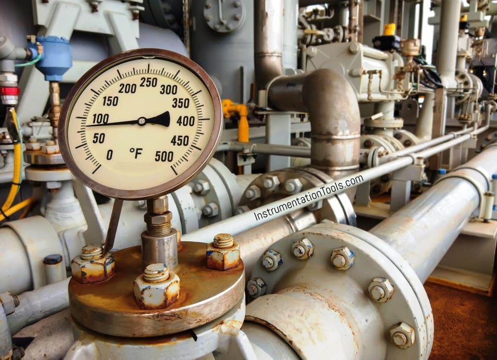
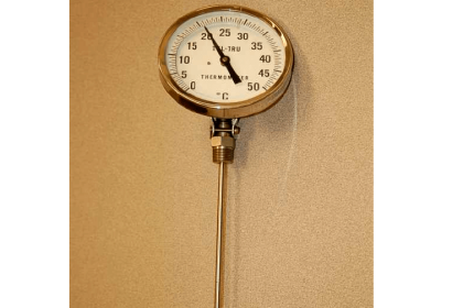
In general applications, the Bimetallic type of gauges are preferred over filled type gauges. These gauges shall have the following features

  • Manufactured according to SAMA class.
  • Case compensation must be provided
  • Temperature bulb material should be SS 316 as minimum

The dial of the gauge shall have following features

  • 150 mm nominal size
  • Black numerals with white background
  • Negative values of temperature should be marked with red color and white background
  • Adjustable head to be provided
  • Provision shall be made for adjustment of pointer without removing from the shaft

Gauges shall have weatherproof construction as per IP66.

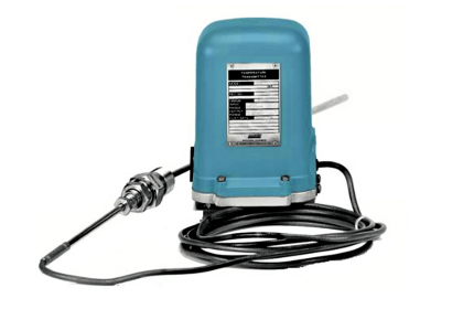
In vibrating conditions, filled type with the capillary extension should be used. The capillary tube shall be made with SS 316 as a minimum. Also, it should have flexible armouring and PVC cover over armouring.

Temperature gauges shall have an accuracy of ± 1% FSD (Full-scale deflection).

Bi-metallic thermometers shall only be used where errors in excess of one percent of the span are acceptable. Bi-metallic dial thermometers shall be every angle, with external pointer adjustment. The case material shall be of SS304. Stem diameter shall be manufacturer’s standard. Bimetallic type dial thermometers shall be avoided where excessive vibrations are encountered, such as compressors.

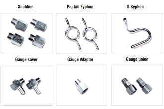
The thermometer stem adjustable gland with union connection and bushing shall be suitable for 1/2″ NPTF connection.

Temperature Gauges and Elements Specifications

Temperature Element Specification

Here we shall see detailed specifications of Temperature elements.

For remote sensing of temperature, thermocouple or RTD is used. Elements shall be spring-loaded, mineral insulated, and shall have 316 SS sheath as a minimum.

Thermocouple

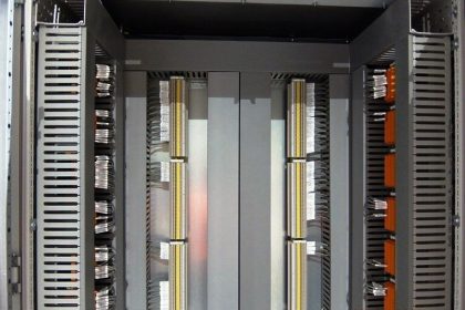
Thermocouple assemblies shall be furnished with weatherproof screwed-in type heads. The terminals shall be color-coded as per element color code.

Thermocouples shall comply with ANSI MC 96.1 and shall be as per IEC-60584-2 / IS -7358. They shall have a wire size of 18 AWG for single and 20 AWG for duplex thermocouples for most of the applications, in general.

Thermocouples shall be magnesium oxide (MgO) filled ungrounded and K-type, unless specified otherwise. The thermocouple wires shall be joined together by welding to form the hot junction.

The design of thermocouple assemblies shall be such that replacement online is possible.

Thermocouple sheathing material shall be 316 stainless steel as a minimum and shall be constructed from a seamless tube with a wall thickness of at least 1mm. Inconel 600 sheath shall be selected for temperatures greater than 600°C.

It shall be ensured that the thermocouples can be bent with a minimum radius of curvature equal to three times the external diameter of the sheath and also at the swaged tip. This operation of the bending shall not result in cracking or rupture of the sheath. The thermocouples shall be bright annealed to achieve this requirement.

The calibration shall be carried out on all the thermocouples according to IEC 584.2 class 1 tolerances. Measurement of e.m.f. shall be done on these thermocouples at six fixed temperature points ranging from 0 to 1000 deg C in accordance with ITS – 90.

The report of the calibration results shall be supplied to the purchaser in a convenient form. This may be a table of values of measured e.m.f at the respective temperature.

The thermoelectric characteristics of the thermocouples shall conform to IEC 584.1 The e.m.f developed by the thermocouple shall be of the order of 41 micro V per Degree Celsius. The law of variation between e.m.f and temperature shall be linear. Also, the accuracy of the measured value shall be better than ± 1.0 degree C up to 350 degrees C & ± 0.4% from 350 to 1000 degree C.

RTD

RTD shall be preferred where the process service temperature is between -200°C to 650 °C.

Connection on the thermowell for RTD should be ½” NPTM.

Cable entry for RTD should be ½” NPTF.

Generally, RTDs shall be 3-Wire, Duplex type with two single wire wound elements compatible with 99.99% pure platinum 100-ohm wire characteristics.

RTD shall generally be selected for applications requiring low-temperature measurement with a comparatively shorter temperature span requiring accuracies of the order of 0.25% or better.

Twin element sensors, if used, shall have two separate cable entries. Multipoint temperature elements shall be provided with an integral junction box.

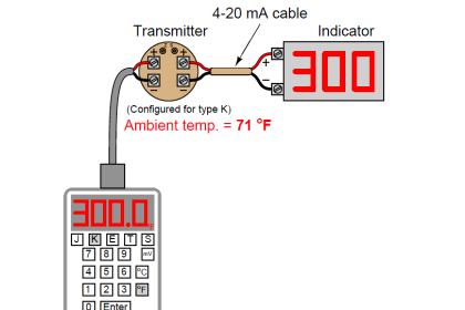
Class ‘A’ / Class ‘1’ tolerance as per IEC 60751 / 60584-2 shall be specified for RTD / thermocouple for temperature measurement in all open and closed loop, interlocking, and shutdown applications. Also, all such loops shall be provided with remote mounted 2 wire temperature transmitters.

Interest to add any further points? Share with us through below comments section.

Author: Kalpit Patel

Read Next:

  • Fault in the Temperature Loop
  • Specification of Thermowell
  • Bi-metal Temperature Sensor
  • Multiple Thermowell Installation
  • Thermocouple Interview Questions
Don't Miss Our Updates
Be the first to get exclusive content straight to your email.
We promise not to spam you. You can unsubscribe at any time.
Invalid email address
You've successfully subscribed !
Differences between No-load Supply Current and Load Current
Thermocouple Calculations
Spiral Bimetallic Thermometer Principle
PLC Analog Signals Wiring Techniques
How to select a load cell?
Share This Article
Facebook Whatsapp Whatsapp LinkedIn Copy Link
Share
1 Comment
  • Rashid Ali says:
    August 31, 2020 at 4:49 pm

    helpful information

    Reply

Leave a Reply Cancel reply

Your email address will not be published. Required fields are marked *

Stay Connected

128.3kFollowersLike
69.1kFollowersFollow
208kSubscribersSubscribe
38kFollowersFollow

Categories

Recent Comments

  • Kamli on Top Free PLC Software
  • Guifty Shimica on Top Non-PLC Certification Courses for Automation Professionals
  • Guifty Shimica on Top Non-PLC Certification Courses for Automation Professionals
  • MIHARITSOA Aina Sitraka on Top Non-PLC Certification Courses for Automation Professionals

Related Articles

RTD Graph

Calculate Temperature Coefficient of RTD

Instrumentation Deliverables Generated from 3D Modeling

Instrumentation Deliverables Generated from 3D Modeling

Pressure Gauge Design

How to Select a Pressure Gauge

Level Gauges

Level Gauge Design

Electrical and Instrument Engineers Job Profile

Instrumentation and Electrical Teams Interactions (Detail Design Engineering)

grounded thermocouple junction

Types of Thermocouple Measuring Junction

Van Stone Type Thermowell

Types of Thermowells

Pneumatic Valves and Cylinders Sizing

Pneumatic Valves and Cylinders Sizing – Part 2

More Articles

Temperature Effect on Wet-Leg System

Effect of Temperature & Pressure on Level Measurement

Network topologies

Different Types of Network Topologies

Burst Transformers Root Cause Analysis

Root Cause Analysis – Burst Transformers and 11 kV Input Breakers

Analog Demodulators Objective Questions

Analog Demodulators Objective Questions

Semiconductor Fuse

What is a Semiconductor Fuse?

NEMA to IP Ratings

NEMA Enclosure Types Standards

PID Controller Types

PID Controllers : Parallel, Ideal & Series

Cobot - Collaborative Robot

What is Cobot? – Collaborative Robot

Follow US
All rights reserved. Reproduction in whole or in part without written permission is prohibited.
Welcome Back!

Sign in to your account

Username or Email Address
Password

Lost your password?